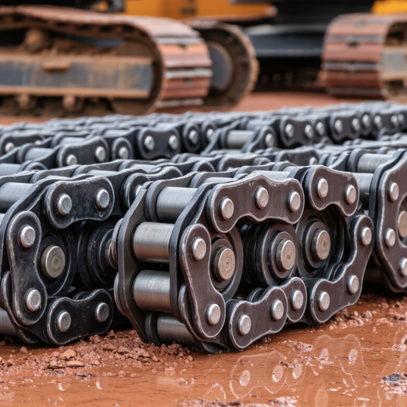
| Product Scope | Track chains for compact and mini excavators generally cover machines below approximately 8 metric tons. | The chain is designed around the excavator's operating weight, track pitch, sprocket profile, roller arrangement, and working environment. | Confirm compatibility using the machine model, track pitch, link count, shoe width, and sprocket tooth profile. |
| Track-Link Material | Medium-carbon or low-alloy steel is commonly selected for strength, toughness, and wear resistance. | Steel billets are cut, heated, and forged into link blanks. Alloy selection depends on the required tensile strength, impact resistance, and heat-treatment response. | Chemical composition is checked by material analysis, while hardness and mechanical properties are tested after heat treatment. |
| Forging Process | Closed-die forging is widely used for production track links because it creates a strong grain flow and repeatable geometry. | A heated steel blank is formed in progressive dies, followed by trimming, piercing, and precision machining of pin and bushing holes. | Dimensional inspection checks hole position, link pitch, link height, alignment, and contact surfaces. |
| Track-Link Heat Treatment | Controlled hardening and tempering are used to balance surface wear resistance with core toughness. | Forged links are heated under controlled conditions, quenched or otherwise hardened, and tempered to reduce brittleness and stabilize performance. | Hardness mapping, metallographic inspection, and dimensional checks are used to verify the treatment result. |
| Pins and Bushings | Pins and bushings require high surface wear resistance while retaining a tougher internal structure. | Round alloy-steel components are machined, heat treated, ground or finished, and matched to the track-link bore and required clearance. | Outside diameter, inside diameter, roundness, surface finish, case hardness, and effective hardened depth are measured. |
| Sealed and Lubricated Design | Sealed track chains are commonly used to retain lubricant and limit the entry of abrasive soil and water. | Seals are installed between the link, pin, and bushing interfaces. The assembly is filled with lubricant before the pin is pressed into the link. | Seal position, press-fit force, lubricant quantity, leakage resistance, and joint articulation are checked during assembly inspection. |
| Track Pitch | Pitch is the center-to-center distance between adjacent track pins and must match the drive sprocket. | Pitch is controlled through forging dies, machining tolerances, pin installation, and final assembly compression. | A calibrated pitch gauge or coordinate measuring equipment checks multiple link intervals rather than only one joint. |
| Link Count | The correct number of links depends on the excavator undercarriage layout and the selected track length. | Individual links are assembled into an endless chain, with the final joint installed after the required link count is confirmed. | The finished chain is counted, measured for overall length, and checked for smooth articulation around a test sprocket or fixture. |
| Surface Protection | Paint, powder coating, or corrosion-protection treatments are commonly applied to exposed steel surfaces. | After cleaning and drying, non-contact surfaces may receive a primer and protective coating. Precision wear interfaces remain controlled to preserve fit. | Coating coverage, adhesion, curing condition, and uncoated dimensional interfaces are inspected. |
| Dimensional Tolerance | Consistent pitch, parallelism, bore alignment, and bushing position are essential for stable sprocket engagement. | CNC machining, dedicated fixtures, controlled press-fitting, and in-process gauges help maintain repeatable assembly dimensions. | Inspection commonly includes bore alignment, link spacing, chain width, pin protrusion, and side-to-side parallelism. |
| Load and Wear Performance | A suitable chain must tolerate repeated tensile loading, articulation, shock loads, and abrasive undercarriage conditions. | Performance is achieved through the combined design of forged links, hardened pins, hardened bushings, controlled clearances, and retained lubricant. | Manufacturers may use tensile, articulation, hardness, wear, fatigue, and endurance tests according to their internal validation plan. |
| Assembly Quality | The finished chain should articulate freely without excessive side play, binding, leakage, or abnormal pitch variation. | Links, pins, bushings, seals, and lubricant are assembled with controlled pressing forces and dedicated tooling. | Final inspection includes visual checks, articulation testing, dimensional sampling, seal inspection, and packaging review. |
| Best Manufacturer Capability Indicators | Reliable suppliers normally demonstrate stable forging, heat treatment, machining, sealing, and traceability processes. | A capable production line integrates material traceability, process control, automated or semi-automated inspection, and documented corrective action procedures. | Review process records, batch traceability, inspection reports, warranty data, and test results rather than relying only on appearance or price. |
| Service-Life Factors | Operating life varies with soil abrasiveness, machine weight, track tension, lubrication condition, sprocket wear, and maintenance practices. | Manufacturers optimize material, hardness, seal design, and clearances, but the final service life also depends heavily on field conditions. | Track wear is monitored through pitch elongation, bushing wear, sprocket condition, seal condition, and abnormal chain movement. |