| Product Classification | UL 489
IEC 60947-2 | Both standards address circuit breakers intended for overcurrent protection. Their test methods, ratings, terminology, and certification systems are not identical. | Confirm which standard is required by the installation location, local electrical code, project specification, or authority having jurisdiction. | Certificate, listing information, conformity documentation, and installation instructions. |
| Rated Voltage | UL 489 / IEC 60947-2 | The maximum system voltage at which the breaker is designed to operate safely. | Select a breaker with a rated operational voltage equal to or higher than the system voltage. Verify AC or DC suitability separately. | Nameplate rating and technical data sheet. |
| Rated Current | In / Ie | The continuous current rating under specified ambient, enclosure, mounting, and temperature conditions. | Choose a rating that protects the conductor and equipment. Do not size the breaker only from the expected load current. | Current rating, derating curves, conductor requirements, and ambient-temperature limits. |
| Interrupting Capacity | UL 489: Interrupting Rating
IEC 60947-2: Icu / Ics | The maximum prospective short-circuit current that the breaker can interrupt at a specified voltage. | The available fault current at the installation point must not exceed the breaker’s applicable interrupting rating. For IEC devices, review both ultimate and service short-circuit ratings where applicable. | Short-circuit calculation, interrupting-rating table, and test conditions. |
| Trip Characteristics | Thermal-Magnetic or Electronic Trip Unit | Protection against overload and short circuit. Electronic units may provide adjustable thresholds, measurement, and event records. | Match long-time, short-time, instantaneous, and ground-fault functions to the load, conductor size, motor starting current, and coordination requirements. | Trip curves, adjustment ranges, tolerances, and coordination study. |
| Frequency and System Type | AC / DC Application Data | Electrical performance can vary with frequency, number of poles, phase configuration, and DC polarity requirements. | Verify system frequency, single-phase or three-phase use, pole arrangement, neutral switching, and any DC polarity restrictions. | Wiring diagram, pole configuration, and application table. |
| Overvoltage Category | IEC 60664-1
Overvoltage Category III | Category III applies to equipment connected in fixed installations, including distribution boards and fixed wiring, where transient overvoltages can be higher than at socket outlets. | For fixed distribution equipment, confirm that the complete assembly and connected devices have insulation coordination suitable for Category III and the declared working voltage. | Insulation-coordination data, rated impulse withstand voltage, clearance, and creepage information. |
| Impulse Withstand | Uimp | The rated impulse withstand voltage indicates the ability of insulation to withstand short-duration transient overvoltages. | Compare the device’s Uimp with the installation’s overvoltage category, system voltage, and required insulation level. Uimp is not the same as continuous operating voltage. | Uimp value, test level, and installation-category declaration. |
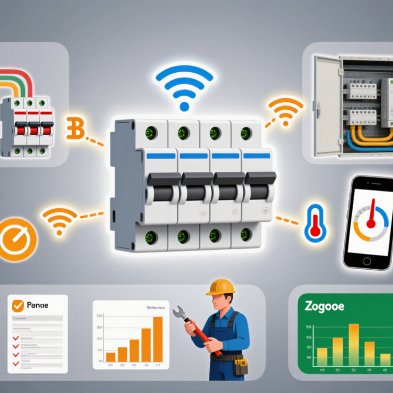
| Smart Monitoring | Communication and Metering Functions | Depending on the design, smart breakers may report voltage, current, power, energy, status, trips, and alarms. | Check measurement accuracy, sampling or update interval, supported parameters, time stamping, local indication, and whether metering remains available during communication loss. | Accuracy specification, register map, event log description, and test report. |
| Remote Operation | Motor Operator or Remote-Control Accessory | Remote open or close functions are separate from the breaker’s basic overcurrent protection and may require mechanical or electrical interlocking. | Confirm remote-control voltage, operating time, manual override, anti-pumping behavior, local lockout, and whether remote closing is permitted after a trip. | Control circuit diagram, operating sequence, and interlock documentation. |
| Communication Security | Network and Access Controls | Connected protection equipment can introduce risks such as unauthorized switching, weak credentials, or exposed control interfaces. | Require unique credentials, role-based access, encrypted communication where supported, firmware-update controls, audit logs, and a method to disable unused interfaces. | Security documentation, update policy, access-control settings, and network diagram. |
| Environmental Conditions | Installation and Enclosure Ratings | Temperature, humidity, altitude, pollution, vibration, and enclosure protection can affect insulation, heating, and operation. | Verify ambient-temperature range, altitude correction, pollution degree, condensation limits, enclosure IP rating, and ventilation requirements. | Environmental specifications, derating charts, and enclosure instructions. |
| Terminal and Wiring Safety | Installation Instructions | Correct conductor material, size, stripping length, torque, terminal arrangement, and spacing are necessary for safe current carrying and insulation performance. | Use only permitted conductor types and sizes. Tighten terminals to the specified torque and provide required separation from adjacent circuits. | Torque table, conductor range, terminal markings, and wiring diagram. |
| Selectivity and Coordination | Protection Coordination Study | Coordination helps ensure that the protective device nearest to a fault operates first, limiting unnecessary interruption of upstream circuits. | Review time-current curves, short-circuit settings, energy-limiting behavior, and manufacturer-tested combinations with upstream and downstream devices. | Coordination curves, tested combinations, and system fault-current data. |
| Functional Safety Check | Commissioning and Periodic Inspection | Smart functions do not replace basic electrical protection, correct installation, or routine inspection and testing. | Test manual operation, trip indication, remote commands, alarm reporting, communication failure behavior, and protective settings before energizing the system. | Commissioning checklist, test records, and maintenance schedule. |