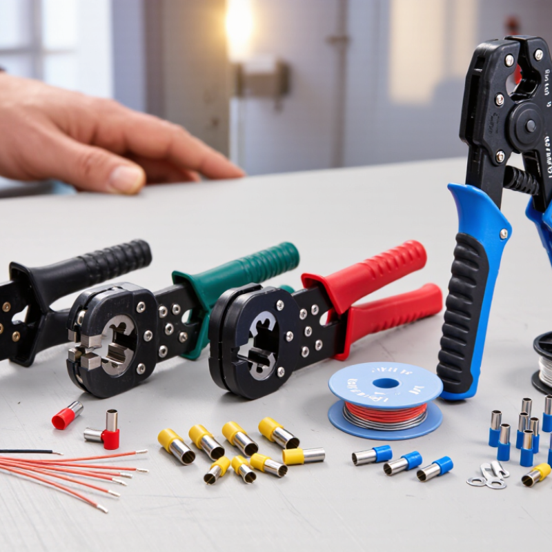
| Basic Definition | A hand crimper is a manually operated tool used to join a wire, cable, or terminal by controlled mechanical deformation. | Commonly used for insulated terminals, non-insulated terminals, wire ferrules, coaxial connectors, and modular plugs. | Closing the handles transfers force through a pivot and jaw assembly, compressing the connector around the conductor. | Choose a tool designed for the exact connector family being installed. |
| Terminal Compatibility | The crimper must match the terminal shape and crimp profile. | Common profiles include indent, oval, hexagonal, square, B-crimp, and modular plug crimping. | Matched dies form the terminal into a controlled profile that holds the conductor mechanically and electrically. | Use dedicated dies when the connector manufacturer specifies a particular profile. |
| Wire Cross-Section | The supported conductor range determines whether the tool can create a secure crimp without damaging the wire. | Typical manual tools cover approximately 0.14–6 mm², while heavy-duty models may cover larger conductors. | The die cavity limits how far the terminal can be compressed for a selected wire size. | Select a range that places the target wire size near the middle of the tool’s rated capacity. |
| American Wire Gauge | AWG is another common way to specify conductor size, especially in electronics and automotive work. | Typical hand-crimper ranges include about 10–26 AWG, depending on the tool and terminal type. | The correct die applies sufficient pressure to the terminal barrel without cutting or flattening the conductor excessively. | Do not convert between mm² and AWG by approximation when working to a safety-critical specification. |
| Crimping Force | Crimping force is the mechanical load required to form the connector correctly. | Light-duty tools may require roughly 80–150 N at the handles; ratcheting and heavy-duty tools require greater effort but provide higher output force. | The lever ratio between the handles and jaws multiplies hand force at the crimping point. | Choose a high-leverage or compound-action model for larger terminals or repeated work. |
| Operating Mechanism | The mechanism affects consistency, required effort, and ease of release. | Common mechanisms include standard pivot, compound-leverage, ratcheting, and self-adjusting designs. | A ratchet prevents the handles from opening until the crimp cycle reaches a defined position, reducing incomplete crimps. | A full-cycle ratchet is generally preferable for repeatable field or production work. |
| Insulated Terminals | These terminals have a plastic sleeve that helps provide electrical insulation and strain protection. | Typical color-coded ranges are red for smaller conductors, blue for medium conductors, and yellow for larger conductors; exact ranges vary by standard. | The die compresses the metal barrel while the insulated section is supported by a separate part of the jaw. | Use a color-coded insulated-terminal crimper rather than a general-purpose plier. |
| Non-Insulated Terminals | These terminals expose the metal barrel and are common in compact electrical assemblies. | Often used with ring, fork, butt, pin, and blade terminals across small and medium wire sizes. | The die forms the barrel directly around the conductor, often producing a controlled indent or oval shape. | Choose a non-insulated terminal die with the correct cavity geometry and size markings. |
| Wire Ferrules | Ferrules prevent stranded wire ends from spreading when inserted into a screw or spring terminal. | Common ferrule crimp profiles include square, hexagonal, and trapezoidal; typical ranges are about 0.25–16 mm² for manual tools. | The die compresses the ferrule sleeve around the strands, creating a compact termination. | Use a ferrule crimper with a profile compatible with the terminal block and ferrule standard. |
| Coaxial Connectors | Coaxial crimpers are designed for cable shields, ferrules, and connector bodies used in signal cables. | Typical cable families include small-diameter radio-frequency and video cables; supported diameters vary by die set. | The die compresses the connector ferrule around the cable shield while preserving the cable geometry. | Select the tool according to cable diameter and connector series, not only by appearance. |
| Modular Plugs | Modular crimpers attach telephone or data plugs to compatible multi-conductor cables. | Common plug formats include 6-position and 8-position modular connectors, with different contact counts and cable layouts. | The tool presses the plug contacts into the conductors and may also secure the cable strain-relief tab. | Confirm plug size, contact count, wiring arrangement, and cable type before crimping. |
| Die Configuration | Dies determine the shape and size of the finished crimp. | Fixed-die tools are faster to use; interchangeable-die tools provide broader connector coverage. | Removable dies can be changed to alter the compression profile without replacing the complete handle assembly. | Choose interchangeable dies when working with several connector families. |
| Handle Length | Longer handles usually provide more leverage but may be less convenient in confined spaces. | Many compact models are approximately 150–200 mm long; larger hand tools may be about 220–300 mm long. | Longer handles increase the moment around the pivot, reducing the hand force needed for the same jaw load. | Use compact handles for access and longer handles for high-force applications. |
| Ergonomics | Grip design, spring action, handle opening, and balance affect comfort and fatigue. | Useful features include nonslip grips, return springs, adjustable handle stops, and reduced handle spread. | Ergonomic features do not change the crimp profile, but they can improve control and reduce repetitive-strain risk. | For frequent use, prioritize comfortable grips and a handle span that fits the operator’s hand. |
| Material and Durability | The frame and dies must withstand repeated compression without excessive wear or deformation. | Common construction includes hardened steel dies, forged or stamped steel frames, and corrosion-resistant surface treatments. | Rigid jaws keep the die aligned so pressure is distributed consistently across the connector barrel. | Look for hardened, accurately aligned dies and a frame with minimal side-to-side movement. |
| Adjustment Capability | Adjustment allows the user to fine-tune crimp depth or compensate for material differences. | Some tools include a pressure-adjustment wheel or indexed setting; others use fixed factory calibration. | An adjustment changes the final jaw position or mechanical stop, altering the amount of terminal compression. | Use adjustable models only when the adjustment range can be verified with pull and visual tests. |
| Crimp Quality Check | A correct crimp must provide both mechanical retention and a reliable electrical connection. | Checks may include visual inspection, conductor-brush inspection, pull testing, and low-resistance measurement. | The crimp should hold the conductor without cutting strands, excessive deformation, cracks, or loose insulation support. | Always inspect the finished crimp and test samples when changing wire, terminal, or tool settings. |
| Application Environment | Indoor panels, automotive systems, telecommunications, and outdoor installations impose different requirements. | Consider vibration, moisture, temperature, available workspace, and the need for sealed connectors. | The hand tool creates the mechanical joint; environmental protection usually comes from the connector, seal, and installation method. | For vibration or moisture exposure, use terminals and seals rated for that environment. |
| Best General-Purpose Choice | A versatile tool should cover common terminal types without sacrificing crimp consistency. | A ratcheting crimper with clear size markings and interchangeable or multi-cavity dies is suitable for many maintenance tasks. | The ratchet controls the cycle while the selected die cavity controls the compression profile. | Choose versatility only when the tool’s die profiles match the connectors used in the project. |
| Important note: The numerical ranges in this table are typical industry ranges for hand-operated tools, not universal specifications. Always follow the terminal, connector, wire, and tooling requirements specified for the particular installation. |