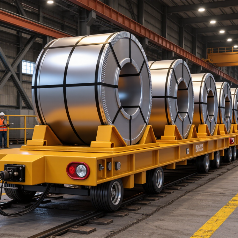
| 1. Set the load envelope | Maximum and minimum coil mass, outside diameter, width, and inside diameter. | Maximum mass: 8,000 kg; outside diameter: 1,200 mm; width: 1,500 mm; inside diameter: 508 mm. | Size the cart and load-support structure for the heaviest and largest permitted coil. Confirm whether the stated mass includes packaging or a pallet, and account for the actual load distribution. |
| 2. Specify coil orientation | State whether the coil travels eye-horizontal or eye-vertical, and whether more than one orientation is required. | Example: eye-horizontal transport, with the coil axis parallel to the floor. | Orientation determines the support arrangement and affects stability, loading, and unloading. Confirm the orientation at pickup and delivery, not only during travel. |
| 3. Choose the load interface | Define how the coil is placed on and removed from the cart, including support shape and contact surfaces. | Example: V-shaped cradle with replaceable, non-marking contact pads; overhead crane loads the coil from above. | Match the cradle geometry to the coil diameter and loading method. Check that the support prevents rolling and does not damage coil edges or surface finishes. |
| 4. Map the travel route | Record route length, aisle width, turning space, door openings, floor joints, ramps, and pickup and delivery positions. | Example: 120 m one-way route; 3.0 m minimum aisle width; maximum floor gradient 1%; two 90-degree turns. | Measure the narrowest and most restrictive points on the loaded route. Verify turning clearance, floor capacity, wheel suitability, and the ability to stop safely on any slope. |
| 5. Define the duty cycle | Estimate trips per shift, operating hours, loaded versus unloaded travel, and expected peak demand. | Example: 20 round trips per day across two 8-hour shifts, with approximately 60% of travel time under load. | Duty affects drive, braking, motor, and power-system selection. Ask suppliers to size equipment against the actual route, payload, stops, and operating schedule. |
| 6. Document the operating environment | Identify indoor or outdoor use, ambient temperature, dust, moisture, washdown, and any hazardous-area requirements. | Example: indoor production hall; 5–40 °C ambient temperature; occasional metal dust; no routine washdown. | Environmental conditions affect electrical protection, components, traction, and maintenance needs. Specify any unusual heat, cold, water, or combustible-dust conditions for engineering review. |
| 7. Set control and safety expectations | Define operating mode, stopping locations, operator visibility, traffic interaction, and required site safety measures. | Example: trained operator uses a pendant control; marked travel lane; audible and visual warnings; emergency-stop access at the controls. | Review the complete route and workplace risk assessment with the supplier. Confirm guarding, braking, warnings, emergency stops, and applicable local regulations before purchase. |