| 1 |
Control Signal |
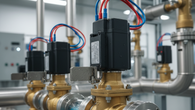
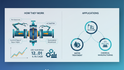
A controller, switch, sensor, or automation system sends an electrical command to the valve actuator. |
Common control signals include on/off commands, relay outputs, and proportional signals such as 0–10 V or 4–20 mA. |
The signal must match the actuator’s rated input and control mode. |
| 2 |
Power Supply |
Electrical power energizes the actuator motor or solenoid coil. |
Common actuator supplies include 12 V DC, 24 V AC/DC, and 120–240 V AC, depending on the design. |
Incorrect voltage can prevent operation or damage electrical components. |
| 3 |
Actuator Operation |
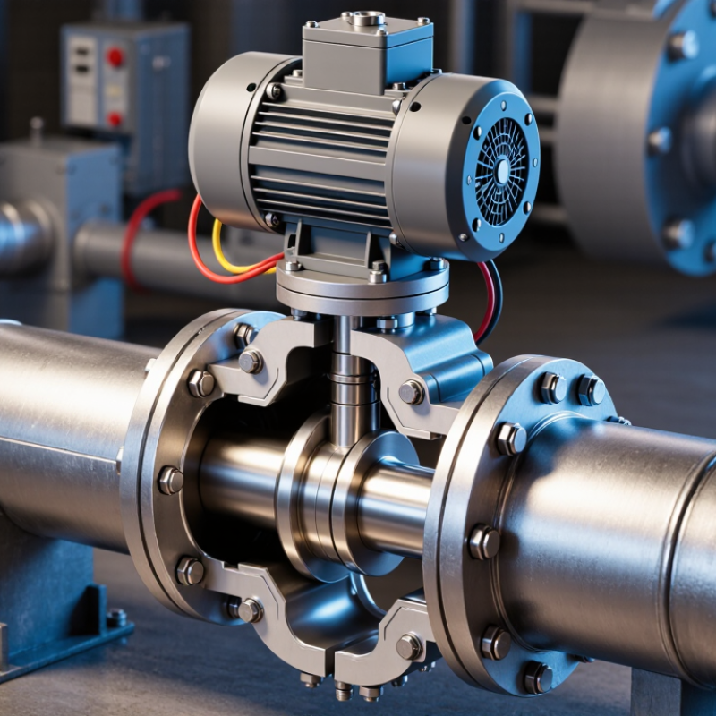
The actuator converts electrical energy into mechanical movement, such as rotary or linear motion. |
Quarter-turn actuators commonly rotate 90 degrees; linear actuators move a stem along a straight path. |
Actuator torque or thrust must be sufficient for the valve’s pressure and flow conditions. |
| 4 |
Stem or Drive Mechanism |
The actuator transfers movement through a stem, gear train, coupling, or linkage to the valve closure element. |
Typical closure elements include balls, discs, plugs, gates, and diaphragms. |
Proper alignment reduces wear, leakage, and mechanical stress. |
| 5 |
Flow Regulation |
The closure element changes position to start, stop, or regulate the flow of liquid, gas, or steam. |
On/off valves normally use fully open or fully closed positions; modulating valves can operate at intermediate positions. |
Valve type and trim must be compatible with the fluid and required flow control. |
| 6 |
Position Feedback |
Limit switches, auxiliary switches, or electronic sensors report whether the valve is open, closed, or at a selected position. |
Feedback can be used for alarms, interlocks, status monitoring, and process control. |
Feedback improves visibility but does not replace correct mechanical installation. |
| 7 |
End of Travel |
When the valve reaches its commanded position, the actuator stops through limit control, electronic control, or motor protection. |
End-of-travel control helps prevent excessive rotation, stem movement, and motor overheating. |
Travel settings should be checked during commissioning and maintenance. |
| 8 |
Fail-Safe Response |
If power is lost, the valve may remain in place or move to a predetermined position, depending on the actuator design. |
Spring-return actuators can move to a normally open or normally closed position after power interruption. |
Fail-safe behavior should be selected according to process safety requirements. |
| 9 |
Control Confirmation |
The controller compares the requested position with the feedback signal and may issue an alarm if the valve does not respond correctly. |
Possible fault conditions include loss of power, blocked movement, wiring errors, and incomplete travel. |
Diagnostics help reduce downtime and support preventive maintenance. |