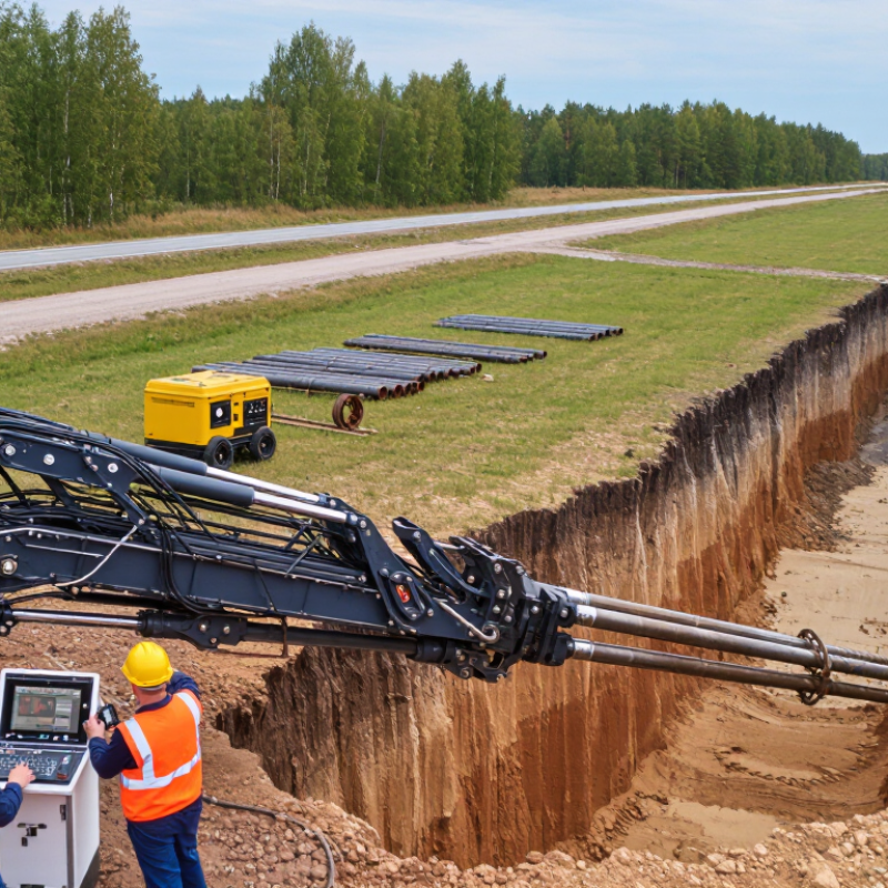
| Drilling Process | Horizontal Directional Drilling (HDD) | A trenchless installation method used to place pipelines, conduits, and cables beneath roads, rivers, railways, and other obstacles. | The work is normally completed in three stages: pilot bore, hole enlargement, and product pullback. | Ground conditions, installation length, required depth, and product size must be evaluated before drilling. |
| Planning and Survey | Site Survey and Utility Locating Equipment | Identifies existing underground utilities, surface restrictions, access points, and the proposed bore path. | May include electromagnetic locating tools, ground-penetrating radar, survey instruments, and utility records. | Accurate utility information helps reduce strike risk and supports safe bore-path design. |
| Primary Equipment | HDD Drilling Rig | Provides thrust, rotation, and controlled movement to advance the drill string through the ground. | Rig capacity is commonly evaluated by pullback force, rotary torque, drilling-fluid flow, and bore length capability. | The rig should be matched to soil conditions, bore diameter, installation length, and product pullback load. |
| Bore Creation | Drill Rods | Transfer rotational force, thrust, and drilling fluid from the rig to the downhole tooling. | Rods are connected in sections and must provide sufficient strength, flexibility, and threaded-joint reliability. | Rod selection depends on bore length, curvature, torque, and the required drilling-fluid pressure. |
| Pilot Bore | Pilot Drill Head | Creates the initial small-diameter bore and allows the operator to steer the drilling path. | Steering is achieved by changing the drill head orientation and controlling thrust and rotation. | The pilot bore establishes the final alignment, grade, entry point, and exit point. |
| Navigation | Downhole Sonde and Locating System | Transmits information about the drill head position, depth, pitch, and direction to the surface operator. | Common systems use a transmitter located behind or near the drill head and a handheld or walkover receiver. | Signal quality can be affected by depth, soil composition, electromagnetic interference, and metallic objects. |
| Bore Enlargement | Reamer or Hole Opener | Enlarges the pilot bore to a diameter suitable for the product being installed. | Reamers are selected according to soil type, required bore diameter, cutting action, and drilling-fluid circulation. | The final bore is often made larger than the product diameter to provide clearance and reduce pullback resistance. |
| Drilling Fluid System | Drilling-Fluid Mixing and Recycling Unit | Mixes, supplies, separates, and recirculates drilling fluid during the operation. | The system may include a mixing tank, pumps, hoses, screens, hydrocyclones, and solids-control equipment. | Fluid management helps control viscosity, remove drilled solids, and limit waste generation. |
| Drilling Material | Bentonite-Based Drilling Fluid | Stabilizes the borehole, transports cuttings, cools tooling, and reduces friction between the product and surrounding soil. | Bentonite is a clay material that forms a gel-like suspension when mixed with water. | Fluid properties should be adjusted for soil conditions and monitored to prevent excessive pressure or inadvertent returns. |
| Drilling Material | Water | Acts as the carrier liquid for bentonite and other approved drilling-fluid additives. | Water quality and supply volume influence mixing performance and fluid consistency. | Local environmental requirements may regulate water use, discharge, and disposal. |
| Soil Conditioning | Drilling-Fluid Additives | Modify fluid properties to improve lubrication, suspension, filtration control, or cuttings transport. | Additives may be selected for reactive clay, sand, gravel, or other challenging ground conditions. | Only suitable materials should be used, and handling must follow safety and environmental requirements. |
| Product Installation | Pullback Swivel and Pulling Head | Connects the reamer to the product and transfers pulling force while reducing torsional stress on the installed product. | The swivel allows rotation of the tooling without transferring the same rotation to the pipe or conduit. | Connections must be compatible with the product size, material, rated load, and planned pullback forces. |
| Installed Product | Polyethylene Pipe | Used for water, gas, wastewater, and other pressure or non-pressure pipeline applications. | Its flexibility and fused joints make it suitable for curved underground alignments. | Pipe wall thickness, allowable pulling force, bend radius, and temperature must be considered. |
| Installed Product | Conduit or Duct | Provides a protected pathway for electrical, telecommunications, control, or fiber-optic cables. | Conduits may be installed individually or in multiple-duct configurations, depending on project requirements. | Minimum bend radius, pulling tension, internal diameter, and cable installation requirements are important. |
| Support Equipment | Drilling-Fluid Pump | Delivers drilling fluid through the drill rods and downhole tooling at the required flow rate and pressure. | Capacity is selected based on bore diameter, soil conditions, tooling design, and desired cutting transport. | Excessive pressure can increase the risk of ground heave or inadvertent drilling-fluid returns. |
| Safety and Control | Pressure, Torque, and Pullback Monitoring | Tracks operating forces and fluid conditions to help control the drilling process. | Important readings include thrust, torque, rotation speed, fluid pressure, flow rate, and pullback force. | Unexpected changes may indicate hard ground, tooling problems, utility conflicts, or bore instability. |
| Completion | Product Pullback | Installs the prepared pipe, conduit, or cable duct by pulling it through the enlarged bore. | Pullback is performed at a controlled speed while maintaining suitable lubrication and alignment. | The product must be inspected for damage, and pullback loads should remain within the allowable limit. |
| Environmental Control | Drilling-Fluid Containment and Disposal System | Controls excess drilling fluid and separates or stores returns generated during drilling. | Methods may include containment tanks, vacuum removal, solids separation, and approved disposal procedures. | Work planning should address inadvertent returns, site cleanup, fluid reuse, and regulatory compliance. |