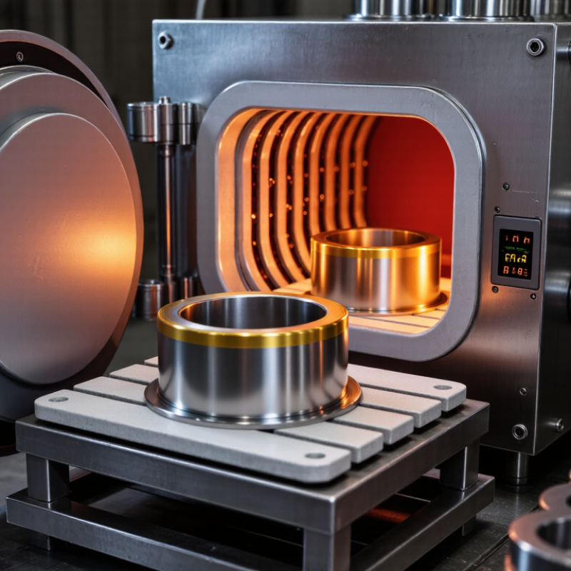
| Cooling begins | Furnace temperature and atmosphere | After the specified brazing hold, the assembly is cooled in the furnace while vacuum is maintained, or with a qualified inert-gas cooling cycle. | Protects hot surfaces from oxidation and keeps the cooling cycle within the approved procedure. |
| Cooling rate | Temperature change through the load | Use the rate established for the part, filler metal, base materials, and furnace load. Avoid abrupt cooling unless the process has been specifically qualified for it. | Limits thermal gradients, distortion, and stress that could damage the joint or assembly. |
| Temperature monitoring | Load and furnace temperatures | Record the furnace cycle using calibrated sensors and the monitoring arrangement specified by the process plan. | Confirms the assembly followed the required cooling cycle; acceptance limits are part- and procedure-specific. |
| Return to safe handling conditions | Part temperature and furnace atmosphere | Keep the assembly in the protected furnace environment until it reaches the temperature at which the approved procedure permits unloading or atmosphere change. | Reduces oxidation risk and helps protect personnel and the assembly during handling. |
| Visual inspection | Joint area and surrounding surfaces | Inspect accessible areas for cracks, incomplete filler flow, excessive filler, visible voids, and signs of distortion or contamination. | Identifies visible defects; visual inspection alone cannot verify the entire internal joint. |
| Dimensional inspection | Critical dimensions and alignment | Measure specified features with suitable calibrated gauges or measuring equipment and compare results with the drawing tolerances. | Confirms that cooling or brazing has not caused unacceptable movement or warpage. |
| Leak testing, when required | Joint integrity in sealed assemblies | Use the specified method, such as a helium mass-spectrometer test or pressure-decay test, with the acceptance limit defined for the component. | Evaluates leakage performance; the appropriate method and limit depend on the design and service requirements. |
| Non-destructive examination, when required | Internal joint features | Radiographic or other qualified examination may be used where joint geometry, material, and inspection requirements make the method suitable. | Can reveal certain internal discontinuities; method capability depends on part geometry and defect type. |
| Process verification | Cycle records and acceptance criteria | Review temperature records, inspection results, and any required test reports against the approved drawing and brazing procedure. | Provides traceable evidence that the assembly met its specified process and quality requirements. |