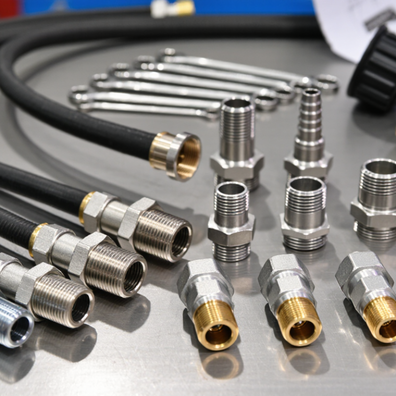
| Thread Standard | Determine whether the port or fitting uses NPT, BSPP, BSPT, or a metric thread. | NPT is a tapered pipe thread covered by ANSI/ASME B1.20.1.
BSPP is a parallel pipe thread commonly designated G under ISO 228-1.
BSPT is a tapered pipe thread commonly designated R under ISO 7-1. | Check the equipment documentation first. If documentation is unavailable, inspect the thread profile, measure the pitch, and compare the outside diameter with a thread chart. | Do not select a fitting only because its nominal size appears similar. NPT, BSPP, and BSPT are different thread systems and are not automatically interchangeable. |
| NPT Thread | Confirm that both mating parts are NPT and that the size designation matches. | NPT uses a 60-degree thread form and a 1:16 taper. The thread itself normally performs the mechanical engagement, while a suitable sealing method is used on the threads. | NPT threads are tapered: the outside diameter gradually changes along the threaded length. Use a calibrated thread gauge or verified dimensional chart for confirmation. | Use an NPT fitting only with a compatible NPT port. Apply a sealant approved for the hydraulic fluid and pressure range when the system design requires thread sealing. |
| BSPP Thread | Confirm the thread is parallel and identify the sealing face or sealing element. | BSPP uses a parallel thread with a 55-degree Whitworth thread form. The thread generally locates and retains the fitting; sealing is typically provided by an O-ring, bonded seal, sealing washer, or another defined interface. | The outside diameter remains substantially constant along the threaded section. Look for an O-ring groove, sealing shoulder, or washer seat. | Match the BSPP thread size and use the specified seal at the port face. Do not rely on thread interference alone unless the fitting design specifically requires it. |
| BSPT Thread | Verify that the port and fitting both use the tapered BSPT system. | BSPT uses a 55-degree Whitworth thread form and a taper. It is a different standard from NPT even though both are tapered pipe threads. | Measure the thread pitch and compare the flank angle and nominal dimensions with the applicable standard. Visual similarity is not sufficient for identification. | Do not substitute BSPT for NPT or NPT for BSPT. Differences in pitch, flank angle, and diameter can cause leakage, thread damage, or unsafe connection strength. |
| Tube Outside Diameter | Measure the actual tube outside diameter rather than relying only on the nominal tube size. | Tube fittings are commonly selected by tube outside diameter. A fractional tube size such as 1/2 inch refers to a 0.500-inch outside diameter in many tube-fitting systems; verification is still required. | Use a calibrated micrometer or vernier caliper on a clean, undamaged section of tube. Measure several points if the tube may be oval or deformed. | Select a fitting that matches the measured tube outside diameter and the tube material, wall thickness, and connection type. |
| Metric Tube Size | Confirm whether the tube is specified in millimeters and record the exact outside diameter. | Metric tube sizes are identified by outside diameter in millimeters, such as 6 mm, 8 mm, 10 mm, or 12 mm. A metric tube should not be treated as an inch tube with a similar nominal dimension. | Measure the tube outside diameter in millimeters and compare it with the fitting specification. Check the thread separately because tube size and port thread are independent dimensions. | Use a metric tube fitting for a metric tube unless the connection is specifically designed and approved for another tube system. |
| Seal Design | Identify where the seal is created: on the thread, at a cone, on a face, or with an O-ring. | Common hydraulic sealing designs include tapered-thread sealing, 24-degree tube cones, 37-degree flare connections, O-ring face seals, and O-ring boss connections. | Inspect the fitting geometry for a cone, flare angle, O-ring groove, bonded washer, or flat sealing face. Never select a seal by thread size alone. | The fitting, port, and seal must share the same sealing design. Replace damaged, flattened, cut, or chemically incompatible seals before assembly. |
| O-Ring Material | Match the elastomer to the hydraulic fluid, temperature, pressure, and environmental conditions. | Elastomer compatibility varies. For example, nitrile rubber is widely used with many petroleum-based hydraulic fluids, while other fluids and temperature ranges may require a different elastomer. | Check the equipment specification or seal material marking. Consider fluid composition, operating temperature, ultraviolet exposure, and chemical contact. | Do not replace an O-ring with an unknown material or an incorrect cross-section. Use the specified size and a fluid-compatible material. |
| Thread Pitch | Confirm threads per inch for inch-based threads or millimeters per thread for metric threads. | Two threads can have similar outside diameters but different pitches. A pitch mismatch may allow partial engagement while preventing reliable sealing or full mechanical strength. | Use a thread pitch gauge. For inch threads, count threads per inch; for metric threads, measure the distance from one thread crest to the next. | Never force a fitting with a different pitch. Cross-threading can permanently damage the port and may create a hidden pressure failure. |
| Pressure and Temperature | Verify the fitting rating for working pressure, impulse pressure, vacuum service, and operating temperature. | The allowable rating depends on the fitting material, size, connection design, tube wall thickness, temperature, and installation method. The weakest component limits the assembly. | Use the applicable technical specification and confirm derating requirements at elevated temperature or under dynamic pressure conditions. | Select a fitting with a working rating suitable for the complete operating envelope, including pressure spikes and temperature extremes. |
| Installation Check | Confirm cleanliness, alignment, torque, and final leak-test requirements. | Contamination, side loading, excessive torque, insufficient tube insertion, and misalignment can cause leakage even when the thread type is correct. | Inspect threads and sealing surfaces, install the fitting according to its connection design, and perform a controlled pressure or leak test before service. | Keep protective caps in place until assembly, avoid mixing sealants with incompatible fluids, and never tighten a pressurized connection. |