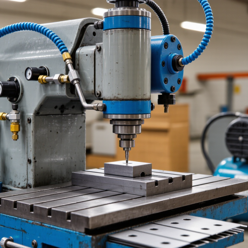
| 1 | Compressed-Air Supply | Provides the energy required to operate the punching actuator. | An external compressor stores and delivers compressed air through piping to the machine. | Common working pressure: approximately 0.5–0.8 MPa, depending on machine design. | Use clean, dry air and size the compressor for both pressure and required air volume. |
| 2 | Air Filter and Water Separator | Removes dust, liquid water, and some contaminants from the air stream. | Incoming air passes through a filter element, while condensed moisture collects in a bowl for drainage. | Typical filtration levels are selected according to the pneumatic system and manufacturer requirements. | Drain accumulated water regularly and replace clogged filter elements. |
| 3 | Pressure Regulator | Controls the air pressure supplied to the actuator. | The regulator reduces upstream pressure to a stable set pressure, helping maintain consistent punching force. | Punching force generally increases with cylinder bore and supplied pressure. | Do not exceed the rated pressure of the cylinder, valve, hoses, or machine frame. |
| 4 | Lubricator | Supplies a controlled amount of oil mist to compatible pneumatic components. | A small quantity of lubricant is carried by the air into valves and cylinders when lubrication is required. | Many modern components are designed for oil-free operation; follow the component instructions. | Avoid adding oil to systems specified as non-lubricated, especially where product contamination is a concern. |
| 5 | Directional Control Valve | Controls the direction of air entering and leaving the cylinder. | A manually, mechanically, or electrically actuated valve sends air to extend or retract the cylinder rod. | Common configurations include 3/2 and 5/2 valves, selected according to actuator type. | Check valve response, air leakage, electrical connections, and exhaust ports. |
| 6 | Pneumatic Cylinder | Converts compressed-air energy into linear mechanical motion. | Air pressure acts on the piston, moving the rod downward to drive the punch and upward for the return stroke. | Theoretical force is approximately F = P × A, where F is force, P is pressure, and A is piston area. | Inspect rod alignment, seals, mounting bolts, and signs of air leakage. |
| 7 | Punch Tool | Cuts, pierces, or forms the workpiece. | The punch moves toward the material and enters or passes through the die opening to create the required shape. | Tool material and geometry depend on the workpiece material, thickness, hole size, and production rate. | Keep the cutting edge sharp and replace damaged tooling to prevent excessive force and poor-quality holes. |
| 8 | Die and Die Holder | Supports the workpiece and provides the opening for the punch. | The clearance between the punch and die allows the material to shear cleanly during the downward stroke. | Required die clearance varies with material type, thickness, and tooling design. | Align the punch and die accurately; incorrect clearance can cause burrs, tool wear, or breakage. |
| 9 | Guide Posts and Bushings | Maintain alignment between the moving punch assembly and the die. | Guiding elements limit lateral movement during the stroke and help maintain consistent tool clearance. | Accuracy depends on guide straightness, fit, rigidity, and regular adjustment. | Keep guide surfaces clean and lubricate only when permitted by the design. |
| 10 | Machine Frame | Supports the cylinder, tooling, worktable, and other operating components. | The rigid frame absorbs reaction forces and keeps the punching mechanism stable during operation. | Frame capacity depends on allowable load, throat depth, working height, and structural rigidity. | Check for cracks, loose fasteners, deformation, and secure anchoring to the floor or workbench. |
| 11 | Worktable and Material Stop | Positions and supports the material during punching. | The workpiece is placed on the table and located against a stop or fixture for repeatable hole placement. | Table size and stop design determine the practical workpiece dimensions and positioning accuracy. | Keep the surface flat, clean, and free from chips that could affect positioning. |
| 12 | Control Button or Foot Pedal | Initiates the punching cycle. | The operator activates the control, which sends a signal to the control valve or controller to start the stroke. | Control mode may be single-cycle, maintained, or two-hand depending on the machine safety design. | Position controls to prevent accidental activation and inspect cables, guards, and switches regularly. |
| 13 | Safety Guard and Interlock | Reduces access to the punch area and helps prevent unintended operation. | A guard blocks access, while an interlock can prevent the cycle from starting when the guard is open. | Safety configuration must match the machine risk assessment and applicable workplace regulations. | Never bypass guards or interlocks; verify their operation before production. |
| 14 | Silencer and Exhaust Port | Releases exhaust air and helps reduce pneumatic noise. | Air leaving the cylinder passes through the valve exhaust port and may be discharged through a muffler. | Exhaust restriction can reduce cylinder speed and affect cycle consistency. | Clean or replace blocked silencers and use hearing protection where noise levels require it. |
| 15 | Stroke and Speed Controls | Adjusts the cylinder travel and movement speed for the punching process. | Flow-control valves regulate air flow, while mechanical stops or sensors can limit the travel distance. | Shorter strokes and controlled speeds can improve cycle time, tool life, and operating consistency. | Set speed gradually; excessive impact speed may damage tooling, material, or the frame. |