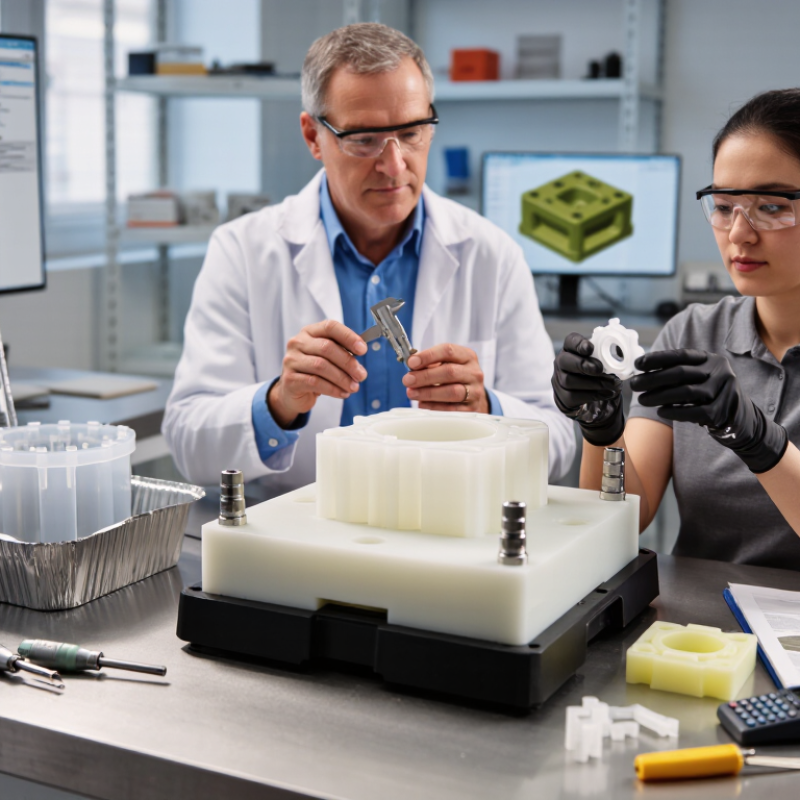
| Primary Purpose | Early-stage functional or visual parts | A mold is created to produce a limited quantity of parts before full-scale production tooling is justified. | Design verification, fit checks, usability testing, and pilot builds | The prototype should reproduce the important geometry, material behavior, and surface requirements of the planned product. |
| Molding Process | Injection molding, compression molding, silicone molding, or urethane casting | The selected material is placed in or injected into a cavity, allowed to solidify or cure, and then removed from the mold. | Parts requiring repeatable dimensions or a production-like appearance | Process choice depends on part size, quantity, required accuracy, material, surface finish, and expected service conditions. |
| Prototype Mold Material | Aluminum, steel, silicone rubber, or epoxy-based tooling materials | The mold material provides the cavity shape and must withstand molding pressure, temperature, and repeated demolding. | Aluminum for short injection runs; silicone for flexible casting molds; steel for higher durability | Aluminum is generally faster to machine than steel, while steel usually offers greater wear resistance and longer tool life. |
| Common Prototype Part Materials | ABS, polypropylene, polycarbonate, nylon, acetal, TPU, silicone, and polyurethane resins | The material is selected to approximate the intended production material or to provide a specific mechanical and visual property. | Functional testing, enclosure prototypes, seals, housings, clips, and ergonomic models | Consider stiffness, impact resistance, heat resistance, chemical exposure, moisture absorption, flexibility, and regulatory needs. |
| Mold Design Inputs | CAD geometry, parting line, draft angles, wall thickness, gates, runners, vents, and ejectors | Engineers convert the part design into a moldable geometry that supports filling, cooling or curing, and part removal. | Most molded prototype parts | Uniform wall thickness and suitable draft help reduce sink marks, warpage, trapped air, and damage during ejection. |
| Draft Angle | Often about 0.5° to 2° or more, depending on texture and geometry | A slight taper allows the molded part to separate from the cavity without excessive friction or surface damage. | Parts with vertical walls or textured surfaces | Textured surfaces and deep features generally require more draft than smooth surfaces. |
| Production Quantity | A few parts to several thousand parts | A lower-cost prototype mold supports limited production while design decisions and test results are still being evaluated. | Engineering validation and low-volume pilot production | Higher quantities can justify more durable tooling, additional cavities, automated ejection, and optimized cycle control. |
| Lead-Time Drivers | Part complexity, mold material, tooling method, material availability, and finishing requirements | Design review, mold fabrication, sampling, inspection, and any required design revisions occur before repeat production. | Projects needing faster feedback than conventional production tooling typically allows | Simple single-cavity molds usually reduce fabrication time compared with complex multi-cavity tools. |
| Dimensional Accuracy | Controlled by mold accuracy, shrinkage, process settings, and material behavior | The mold cavity defines the part, but cooling, curing, and material shrinkage can affect final dimensions. | Fit and function testing where critical tolerances are identified in advance | Critical dimensions should be specified on the drawing and verified through inspection of trial parts. |
| Surface Finish | As-machined, polished, textured, painted, or chemically finished | The mold surface transfers its texture or smoothness to the molded part, with optional post-processing afterward. | Appearance models, user-interface parts, visible housings, and consumer-product studies | Surface texture can influence draft requirements, release performance, gloss, and the visibility of molding marks. |
| Quality Checks | Visual inspection, dimensional measurement, material verification, and functional testing | Trial parts are compared with drawings, CAD data, test requirements, and acceptance criteria before the mold is approved. | Any prototype program where test results will guide design or production decisions | Inspection should focus on critical dimensions, warpage, flash, short shots, sink marks, weld lines, and surface defects. |
| When to Move to Production Tooling | After design, material, performance, and manufacturability are sufficiently validated | Test findings are incorporated into the final design before investing in higher-volume tooling. | Stable designs with confirmed demand and production requirements | Review expected annual volume, tool life, cycle time, automation, cavity count, maintenance, and long-term material requirements. |