| 1. Start with the operation | General external turning | 80° diamond (C-style) | A general-purpose chipbreaker; choose a positive rake for lower cutting forces or a stronger, more negative geometry for heavier cuts. | The robust included angle suits a broad range of turning tasks. Check that the holder and workpiece clearance accommodate the insert. |
| 2. Prioritize access for profiling | Contour turning and profiling | 55° diamond (D-style) or 35° diamond (V-style) | A sharper included angle and suitable clearance can improve access to contours; use a positive-rake geometry when lower cutting forces are important. | Narrower-angle inserts reach tighter profiles, but have less edge support. Confirm clearance and avoid excessive depth or impact for the chosen edge strength. |
| 3. Match the edge to shoulders | Facing and turning square shoulders | 90° square (S-style) or 80° diamond (C-style), depending on access | Select a tool approach angle and insert clearance that allow the tool to reach the shoulder without rubbing. A stable edge is useful for interrupted cuts. | Check the holder orientation and machine clearance. The insert shape alone does not guarantee a true square shoulder. |
| 4. Choose a corner radius for the finish and load | Finishing or rough turning | Shape suited to the profile, with an appropriate nose radius | A smaller nose radius can reduce cutting forces and help with fine details; a larger radius generally strengthens the corner and can support a higher feed when the setup is rigid. | Balance finish requirements against chatter risk, feed rate, workpiece rigidity, and corner strength. Follow the insert maker’s recommended cutting data for the specific grade and geometry. |
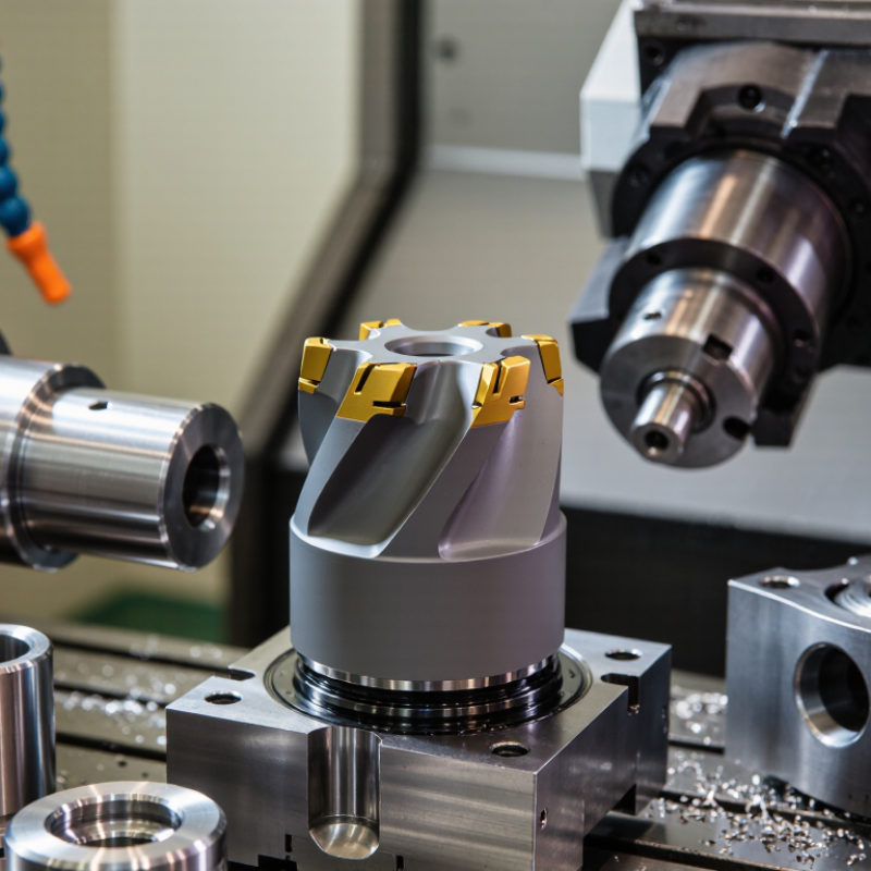
| 5. Consider a round edge for milling | Face milling and other milling cuts with changing engagement | Round (R-style) insert | A circular cutting edge distributes load over a changing contact area; select a suitable rake and edge preparation for the material and cut. | Round inserts can be effective in milling, but cutting forces can be substantial. Check power, rigidity, engagement, and the recommended depth of cut. |
| 6. Match chip control to the cut | Finishing, medium turning, or roughing | Any compatible shape with an operation-specific chipbreaker | Chipbreaker grooves are designed for particular ranges of feed and depth of cut. Finishing geometries often suit lighter cuts; roughing geometries are typically more robust. | Choose a chipbreaker for the actual feed, depth, material, and cutting direction. If chips are long or the edge wears unusually, review the geometry and cutting conditions. |
| 7. Verify the full setup | Any turning or milling operation | Shape that fits the holder, tool path, and workpiece access | Check insert clearance, edge preparation, rake, corner radius, clamping, and whether the cut is continuous or interrupted. | Treat shape and geometry as part of a complete tool system. Confirm compatibility with the holder and use cutting data appropriate to the workpiece material and machine setup. |