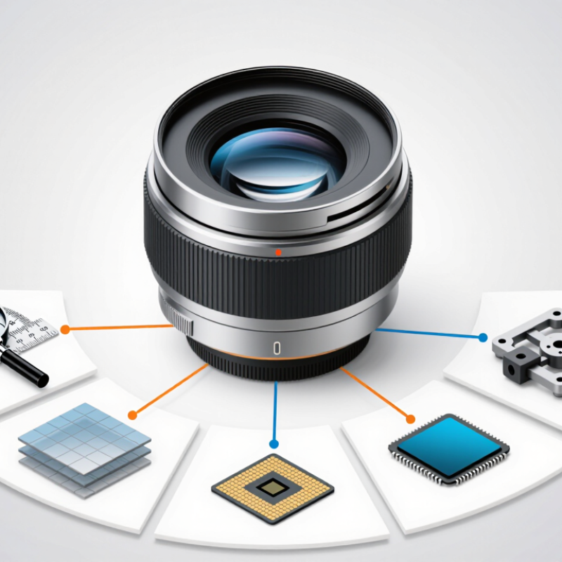
| 1 | Match the sensor format | Choose an image circle at least 10% larger than the sensor diagonal. For a 1-inch sensor with a 15.9 mm diagonal, specify an image circle of at least 17.5 mm. | A telecentric lens with an undersized image circle can produce dark corners, reduced illumination, or vignetting. | Compare the lens image-circle specification with the actual sensor width, height, and diagonal. |
| 2 | Match resolution to pixel pitch | The lens must resolve detail appropriate for the camera pixel pitch. Approximate sensor Nyquist frequency is calculated as 1 ÷ (2 × pixel pitch). | A high-megapixel camera does not automatically deliver higher usable detail if the lens MTF is insufficient. | Request MTF data at the intended wavelength, working distance, aperture, and field position. |
| 3 | Select the required magnification | Use magnification = sensor active width ÷ object-field width. Example: a 13.2 mm sensor width covering a 66 mm object width requires approximately 0.20× magnification. | Magnification determines the field of view, object sampling, working distance, and available lens options. | Calculate field of view separately for the horizontal and vertical sensor dimensions. |
| 4 | Check telecentricity and perspective error | For dimensional inspection, prioritize a specified object-space telecentricity, commonly expressed as less than 0.1% to 0.5%, depending on accuracy requirements. | Low telecentric error minimizes apparent size changes caused by object movement along the optical axis. | Confirm the telecentricity specification across the usable field and working-distance range. |
| 5 | Verify working distance and depth of field | Select a nominal working distance that leaves room for lighting, fixtures, and product variation. Increasing f-number generally increases depth of field but reduces light and may lower diffraction-limited resolution. | A lens that fits the sensor but not the mechanical envelope can be unusable in the inspection system. | Test the nearest and farthest object surfaces at the intended aperture. |
| 6 | Control illumination and aperture | Telecentric lenses often benefit from coaxial, dome, backlight, or collimated illumination. Use the lens aperture within its specified range and avoid operating only at the minimum f-number when uniformity is critical. | Lighting geometry strongly affects edge contrast, glare, surface reflections, and measurement repeatability. | Check corner-to-center illumination and image contrast with the real product and lighting setup. |
| 7 | Confirm interfaces and calibration | Verify mount type, filter-thread clearance, sensor cover-glass compatibility, mechanical back focal distance, and distortion data. Calibrate with a traceable grid or certified artifact when dimensional accuracy is required. | Mechanical compatibility and calibration determine whether the theoretical optical performance becomes reliable measurement data. | Measure distortion, scale, repeatability, and residual error after final installation. |