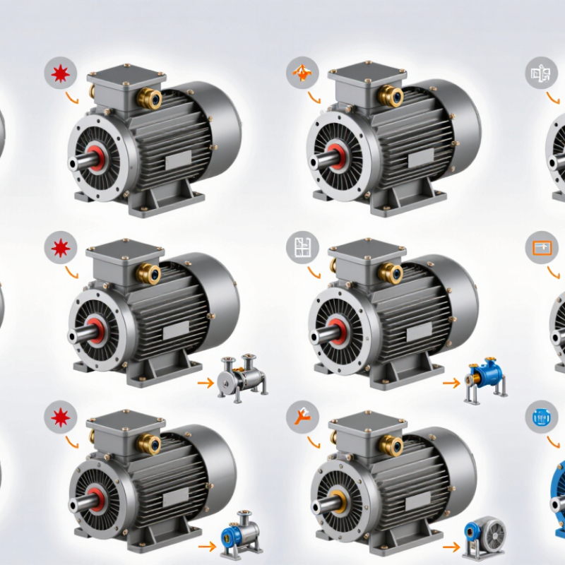
| 1 | Standard Top-Mounted Flameproof Box | One main Ex d terminal chamber with bolted cover | Top entry; cable glands selected for the cable type and certification | Zone 1 / Zone 2 | IIA, IIB; IIC when specifically certified | T4; T3 or T5/T6 subject to design and certification | Approximately 0.12–315 kW | General-purpose process equipment and fixed industrial drives |
| 2 | Side-Mounted Flameproof Box | Ex d chamber positioned on the motor side for improved access | Left- or right-side mounting; horizontal cable entry | Zone 1 / Zone 2 | IIA / IIB; IIC only with applicable certification | T4 commonly specified | Approximately 0.75–250 kW | Skid-mounted pumps, compressors and equipment with limited top clearance |
| 3 | Rotatable Terminal-Box Design | Terminal box designed for approved 90° position changes | Flexible cable direction; rotation must preserve certified joints and sealing | Zone 1 / Zone 2 | IIA, IIB or IIC according to certificate | T4 typical; other classes are application-dependent | Approximately 1.1–200 kW | Retrofit projects and installations where cable routing varies by site |
| 4 | Two-Compartment Flameproof Box | Separate power-terminal and auxiliary-terminal chambers | Independent entries for power, sensors and control wiring | Zone 1 / Zone 2 | IIA / IIB; IIC available only in certified versions | T4 commonly used | Approximately 7.5–315 kW | Motors requiring separate instrumentation, anti-condensation heaters or RTDs |
| 5 | Large-Cable / High-Current Box | Deep Ex d chamber with enlarged terminals and increased creepage distance | Large metric or NPT entries; gland size depends on cable diameter | Zone 1 / Zone 2 | IIA / IIB; IIC subject to tested enclosure configuration | T3 or T4 depending on motor loading | Approximately 90–1,000 kW | Large pumps, fans, compressors and high-inertia machinery |
| 6 | IIC-Optimized Compact Box | Compact Ex d enclosure using certified narrow flame paths and terminal spacing | Compact side or top entry; only approved glands and plugs may be used | Zone 1 / Zone 2 | IIC | T4; T3 or T6 where specifically certified | Approximately 0.12–90 kW | Hydrogen, acetylene or other high-risk gas-group applications within certificate scope |
| 7 | Instrumented Flameproof Box | Power terminals plus dedicated terminals for RTDs, thermistors and heaters | Multiple sealed entries with segregated low-voltage wiring | Zone 1 / Zone 2 | IIA / IIB; IIC if the complete assembly is certified | T4 typical | Approximately 5.5–500 kW | Continuous-process plants requiring condition monitoring and thermal protection |
| 8 | Vertical-Shaft Motor Box | Flameproof box positioned for vertical motor installation and service access | Top, side or remote entry depending on vertical layout | Zone 1 / Zone 2 | IIA / IIB; IIC by certified design | T4 commonly specified | Approximately 1.5–250 kW | Vertical pumps, agitators and cooling-tower equipment |
| 9 | Remote-Terminal / Extended-Box Design | Terminal enclosure offset from the main frame by a certified extension | Used where direct access is obstructed; extension length is design-specific | Zone 1 / Zone 2 | IIA / IIB; IIC only when covered by certification | T4 typical | Approximately 15–500 kW | Motors installed behind guards, in congested skids or near hot equipment |
| 10 | Split-Entry Flameproof Box | Multiple certified entry plates for separate power and auxiliary cable routes | Opposite-side or multi-directional entries; unused openings require certified stopping plugs | Zone 1 / Zone 2 | IIA, IIB or IIC according to the approved entry system | T4 typical; final class depends on motor surface temperature | Approximately 11–315 kW | Complex installations with separate VFD, control, heater and instrumentation cables |