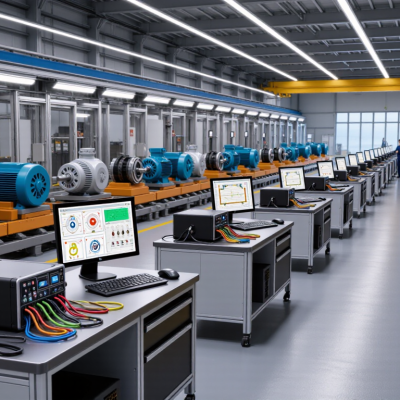
Stator testers evaluate the electrical health of motor windings through controlled, repeatable measurements.
They check resistance, insulation strength, inductance, and phase balance. Each function reveals a different fault pattern.
A resistance test sends a low current through each winding. The tester compares readings between phases. Large differences may indicate loose connections, broken conductors, or partial winding damage.
Insulation resistance testing applies a controlled DC voltage between windings and the core. It measures leakage current and calculates insulation resistance.
A hipot test uses higher voltage for a short period. This can expose weak insulation, but it requires strict grounding and safety procedures.
Surge testing sends brief high-voltage pulses into the winding. Reflected wave differences can reveal turn-to-turn faults that ordinary resistance tests may miss.
The method is sensitive and needs suitable voltage settings.
In repair workshops, technicians usually combine several tests instead of trusting one reading.
Temperature affects copper resistance, so measurements should be corrected or compared under similar conditions. Clean terminals matter. Dust and moisture can distort insulation results.
A perfect display does not always prove a healthy stator; mechanical damage may remain invisible. I have found that test records are often less complete than the equipment itself.
Recording phase values, ambient temperature, test voltage, and operator notes improves traceability.
Some testers also support automatic sequences, waveform analysis, and data export, but automation can hide poor setup. Experienced users still inspect leads, confirm connections, and question unusual results.