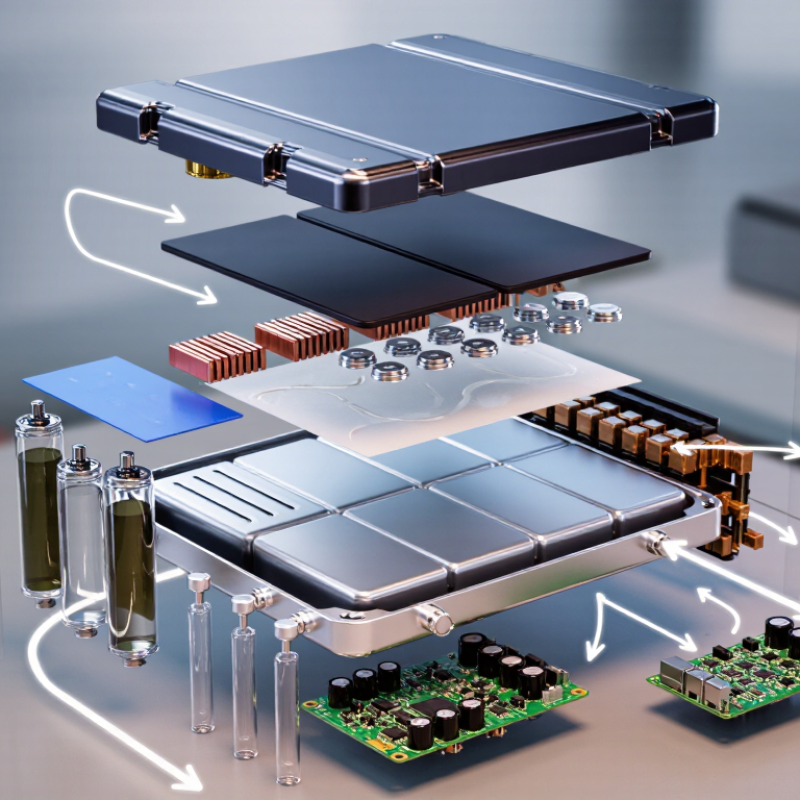
| Cathode Active Material | Stores and releases lithium ions during charge and discharge. | Lithium iron phosphate (LFP), nickel-manganese-cobalt oxide (NMC), or lithium nickel manganese oxide (LNMO). | Particle-size distribution: controlled by application
Moisture: low ppm-level specification
Metal impurity control: required for copper, iron, sodium, and other contaminants | Incoming chemical analysis, moisture testing, tap-density measurement, particle-size analysis, and electrochemical sample-cell validation. | Raw-material lot, synthesis batch, test report, production date, storage conditions, and shipment lot. | When matched with a suitable cell design and operating profile, LFP systems are commonly selected for applications targeting more than 1,000 cycles. | IEC 62660-1 UN 38.3 ISO 9001 |
| Anode Active Material | Accepts lithium ions during charging and releases them during discharge. | Natural graphite, synthetic graphite, silicon-graphite composite, or lithium titanate for specialized designs. | Reversible capacity: chemistry-dependent
Particle morphology: consistent and application-specific
Surface area and moisture: controlled to reduce side reactions | Particle-size distribution, specific-surface-area testing, moisture analysis, impurity screening, and half-cell or full-cell performance checks. | Graphite source lot, coating or treatment batch, laboratory results, warehouse humidity record, and final release approval. | Graphite-based anodes can support more than 1,000 cycles when paired with compatible cathode chemistry, electrolyte, formation process, and thermal controls. | IEC 62660-1 ISO 9001 ISO 14001 |
| Separator Film | Prevents direct contact between the electrodes while allowing ionic conduction. | Microporous polyethylene (PE), polypropylene (PP), PP/PE/PP multilayer film, or ceramic-coated polyolefin. | Thickness: commonly about 10–30 µm
Porosity: typically application-controlled
Mechanical strength: sufficient for winding or stacking
Shutdown behavior: required for selected designs | Thickness uniformity, porosity, air permeability, puncture strength, tensile strength, shrinkage, and visual-defect inspection. | Film-roll number, resin lot, coating batch, slitting records, inspection results, and storage-condition history. | Cycle life depends on separator chemistry, electrolyte compatibility, cell pressure, temperature, and abuse resistance; no universal cycle value applies to the separator alone. | IEC 62660-3 UL 2580 ISO 9001 |
| Electrolyte | Provides ionic transport between the cathode and anode. | Lithium salt, commonly LiPF6, dissolved in carbonate-based solvents with selected additives. | Water content: controlled at low ppm levels
Conductivity: formulation-specific
Flash point and viscosity: matched to cell design
Additive package: selected for cycle and storage stability | Water analysis, density, viscosity, conductivity, acidity, ionic impurity, visual clarity, and container-integrity checks. | Salt lot, solvent lot, additive batch, mixing record, filling date, container seal, and cold-chain or storage record when applicable. | Proper formulation and moisture control are essential for achieving a cell-level target of 1,000+ cycles; electrolyte performance is application-dependent. | IEC 62660-1 UN 38.3 SDS |
| Current Collectors | Conduct electrical current between the active materials and external terminals. | Aluminum foil for the cathode and copper foil for the anode. | Thickness: commonly about 6–20 µm
Width and edge quality: matched to electrode design
Surface cleanliness: free from oil, burrs, and metallic particles | Thickness mapping, tensile strength, elongation, surface roughness, pinhole inspection, burr measurement, and winding compatibility. | Metal coil number, rolling batch, foil-slitting record, surface-treatment batch, inspection report, and shipment lot. | Collectors do not have an independent cycle-life rating; their resistance, adhesion, corrosion resistance, and dimensional stability influence cell life. | IEC 62660-1 IATF 16949 ISO 9001 |
| Electrode Coating | Applies the cathode or anode active mixture uniformly onto the current collector. | Active material, conductive additive, binder, and solvent system selected for the electrode chemistry. | Coating loading: controlled by energy and power requirements
Thickness uniformity: tightly controlled across the web
Adhesion: sufficient to resist cracking and delamination | Wet and dry coating-weight checks, thickness mapping, adhesion testing, porosity measurement, edge inspection, and residual-solvent control. | Mixing batch, coating line, operator or shift record, slurry viscosity, drying profile, roll number, and nonconformance history. | Uniform coating and stable calendaring are major contributors to consistent capacity retention and cell-level performance beyond 1,000 cycles. | IEC 62660-1 IATF 16949 ISO 9001 |
| Cell Housing and Cover | Encloses the electrochemical stack and protects it from mechanical, environmental, and electrical hazards. | Aluminum alloy pouch, cylindrical steel, or prismatic aluminum housing, depending on cell format. | Dimensional tolerance: matched to module design
Sealing performance: leak-tight after assembly
Pressure-relief design: appropriate for cell format
Corrosion resistance: verified for the intended environment | Dimensional inspection, weld or seal-strength testing, helium or pressure-leak testing, insulation resistance, and pressure-relief verification. | Metal or film lot, forming batch, welding parameters, sealing record, leak-test result, and final inspection data. | Housing life is evaluated as part of the complete cell; mechanical integrity and sealing must remain stable throughout the intended cycle and calendar life. | IEC 62619 UL 2580 UN 38.3 |
| Terminals, Tabs, and Insulation | Transfers current from the electrode stack and prevents unintended electrical contact. | Nickel-plated steel, aluminum, copper, nickel, polymer insulation films, and electrical tapes. | Electrical resistance: low and consistent
Weldability: compatible with assembly process
Insulation rating: suitable for maximum system voltage and temperature | Weld-pull testing, contact-resistance measurement, insulation-resistance testing, dimensional inspection, and contamination checks. | Terminal material lot, plating batch, welding program, pull-test record, insulation material lot, and inspection release. | Stable connections help prevent localized heating and resistance growth, supporting the complete cell’s intended cycle-life target. | IEC 62619 UL 2580 IEC 62133-2 |
| Battery Management System (BMS) | Monitors voltage, current, and temperature while managing protection, balancing, estimation, and communication. | Voltage and temperature sensors, protection switches, control processor, balancing circuit, communication interface, and firmware. | Voltage accuracy: application-specific
Temperature monitoring: multiple sensing points as required
Protection functions: overcharge, over-discharge, overcurrent, short circuit, and over-temperature
Communication: CAN, UART, or other defined protocol | Functional testing, protection-threshold verification, sensor calibration, firmware validation, communication testing, and fault-injection testing. | PCB lot, component date codes, firmware version, calibration record, programming record, test fixture ID, and serial-number association. | A correctly configured BMS is essential to protect cells and help maintain a system target of 1,000+ cycles; the BMS does not create cycle life independently. | IEC 62619 UL 1973 ISO 26262 |
| Thermal Management Materials | Controls heat transfer and limits temperature differences between cells during operation. | Thermal interface pads, gap fillers, graphite sheets, cooling plates, phase-change materials, or liquid-cooling components. | Thermal conductivity: selected for the heat-load profile
Compression set: compatible with module assembly
Electrical insulation: required where specified
Operating temperature: matched to the battery environment | Thermal-conductivity testing, thickness and compression checks, adhesion inspection, dielectric testing where applicable, and aging evaluation. | Material lot, formulation or cure batch, thickness record, supplier test report, installation location, and assembly torque or compression data. | Keeping cells within a controlled temperature range helps reduce capacity loss and resistance growth, supporting long-life designs above 1,000 cycles. | IEC 62619 UL 1973 ISO 16750 |
| Module and Pack Enclosure | Provides mechanical protection, environmental sealing, mounting interfaces, and system-level safety. | Aluminum, coated steel, engineering polymers, gaskets, fasteners, and flame-retardant materials. | Ingress protection: defined by application, such as IP-rated designs
Structural strength: verified under vibration and shock
Flammability: suitable for the system risk assessment
Service access: compatible with maintenance requirements | Dimensional inspection, torque verification, ingress testing, vibration and shock testing, grounding continuity, insulation testing, and thermal-event assessment. | Enclosure material lot, gasket lot, fastener batch, torque record, assembly line, serial-number mapping, and final inspection report. | The enclosure supports system durability but has no standalone cycle-life rating; complete-pack life depends on cell chemistry, controls, temperature, and load profile. | IEC 62619 UL 1973 UN 38.3 |