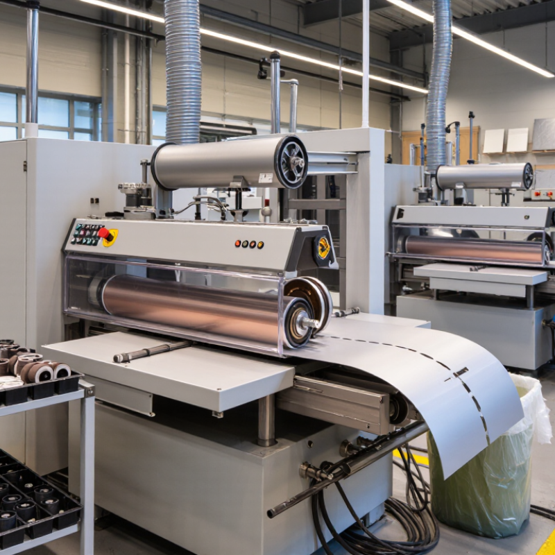
| Working Width | 600–1,600 mm is a common range for industrial wide belt machines; wider custom systems are available. | Determines the maximum sheet, plate, or panel width that can be processed in one pass. | Stainless-steel sheets, carbon-steel plates, aluminum components, and fabricated panels. | Confirm the usable sanding width rather than the machine’s overall frame width. |
| Abrasive Belt Length | Approximately 1,900–2,620 mm on many standard configurations. | Longer belts generally provide more abrasive surface area and can support stable heat distribution. | Continuous deburring, surface preparation, and finish sanding. | Check belt dimensions and compatibility with the required abrasive material. |
| Number of Sanding Heads | One to four heads, with two- and three-head layouts frequently used for staged processing. | Multiple heads allow material removal, intermediate sanding, and finishing in a single pass. | Laser-cut part deburring, weld-scale removal, and cosmetic finishing. | Review the head sequence, abrasive grades, and maximum stock-removal capability. |
| Abrasive Belt Speed | Commonly adjustable from about 10 to 30 m/s, depending on the abrasive head and material. | Speed affects cutting performance, surface roughness, heat generation, and abrasive life. | Heavy grinding of mild steel and controlled finishing of stainless steel. | Make sure the speed range matches the recommended operating speed of the abrasive belt. |
| Feed Speed | Typically adjustable from approximately 3 to 25 m/min on production machines. | Variable feed speed helps balance throughput, stock removal, surface finish, and heat input. | High-volume sheet processing and repeatable batch production. | Check whether feed speed is controlled by an inverter or servo drive. |
| Workpiece Thickness | Often about 0.5–120 mm, depending on the conveyor, pressure system, and machine configuration. | A broad thickness range improves production flexibility across different metal parts. | Thin sheet, medium-gauge plate, brackets, frames, and fabricated assemblies. | Verify the minimum thickness, maximum thickness, and automatic thickness compensation. |
| Material Removal | Light deburring to several tenths of a millimeter per pass; actual removal depends on metal, abrasive, and head design. | Indicates whether the machine is suited to edge rounding, scale removal, or true stock removal. | Removing oxide layers, burrs, weld discoloration, and machining marks. | Request test results using the actual workpiece material and target removal rate. |
| Contact Roller or Sanding Pad | Steel or rubber contact rollers, sanding pads, brush heads, and combination configurations are available. | Head type influences cutting action, edge treatment, finish uniformity, and contour compliance. | Flat-surface grinding, edge rounding, satin finishing, and uniform surface preparation. | Confirm roller hardness, pad pressure control, and compatibility with the intended finish. |
| Conveyor System | Steel or rubberized conveyor belts with automatic tracking and adjustable hold-down pressure. | Stable conveying supports consistent thickness control and reduces workpiece movement. | Flat sheets, cut blanks, plates, and repeat-production components. | Inspect conveyor load capacity, tracking method, and replacement-belt availability. |
| Thickness Control | Manual, motorized, or CNC-controlled table adjustment; digital position displays are common on modern systems. | Accurate adjustment helps maintain repeatable material removal and dimensional consistency. | Precision surface preparation and production lines with recurring part specifications. | Check adjustment resolution, calibration procedure, and closed-loop control options. |
| Dust and Spark Management | Enclosed sanding zones with extraction ports; spark arrestors and wet-working options may be available. | Effective extraction improves visibility, protects components, and reduces airborne metal dust. | Dry sanding of steel, stainless steel, aluminum, and mixed-metal parts. | Confirm required airflow, duct diameter, spark protection, and combustible-dust safeguards. |
| Drive Power | Installed power commonly ranges from roughly 20 to 150 kW for multi-head industrial equipment. | Higher power supports greater stock removal and wider working widths but increases energy demand. | Heavy grinding, continuous production, and wide-plate processing. | Compare total installed power, individual motor ratings, and facility electrical capacity. |
| Control System | PLC-based controls with touch-screen interfaces, recipe storage, overload monitoring, and emergency-stop circuits. | Automation improves repeatability, setup speed, fault diagnosis, and operator protection. | Contract manufacturing, automated fabrication cells, and multi-shift production. | Review control-language options, data access, remote diagnostics, and software support. |
| Safety Features | Guarded sanding heads, emergency-stop buttons, access-door interlocks, overload protection, and belt-break detection. | Safety systems help control hazards from rotating parts, abrasive failure, sparks, and unexpected movement. | General metalworking environments and production lines with multiple operators. | Check conformity with applicable local machinery, electrical, and workplace-safety requirements. |
| Surface-Finish Control | Finishes can range from aggressive mill-scale removal to brushed or satin surfaces by changing abrasive type, grit, pressure, and speed. | Process flexibility allows one platform to handle preparation and cosmetic finishing tasks. | Architectural stainless steel, appliance parts, enclosures, and painted-surface preparation. | Specify the required roughness value, visual standard, and direction of the final grain. |
| Maintenance Access | Large service doors, centralized lubrication points, quick belt-change mechanisms, and accessible filters are preferred features. | Good access reduces downtime and simplifies routine inspection and abrasive replacement. | High-utilization plants and facilities with preventive-maintenance programs. | Evaluate access to rollers, bearings, conveyors, dust ducts, and electrical cabinets. |
| Typical Machine Footprint | Approximately 2.5–7.5 m long and 1.5–3.5 m wide, depending on width, number of heads, and auxiliary equipment. | Footprint affects factory layout, material flow, operator access, and installation cost. | Standalone production cells and integrated sheet-metal processing lines. | Allow additional space for loading, unloading, maintenance, extraction, and electrical services. |
| Best Selection Criteria | Match working width, material type, stock removal, finish requirement, throughput, automation level, and extraction method. | A correct specification prevents underpowered operation, poor finishes, excessive abrasive consumption, and avoidable downtime. | New equipment purchases, line upgrades, and replacement of manual grinding operations. | Use production trials and a written acceptance specification before final procurement. |