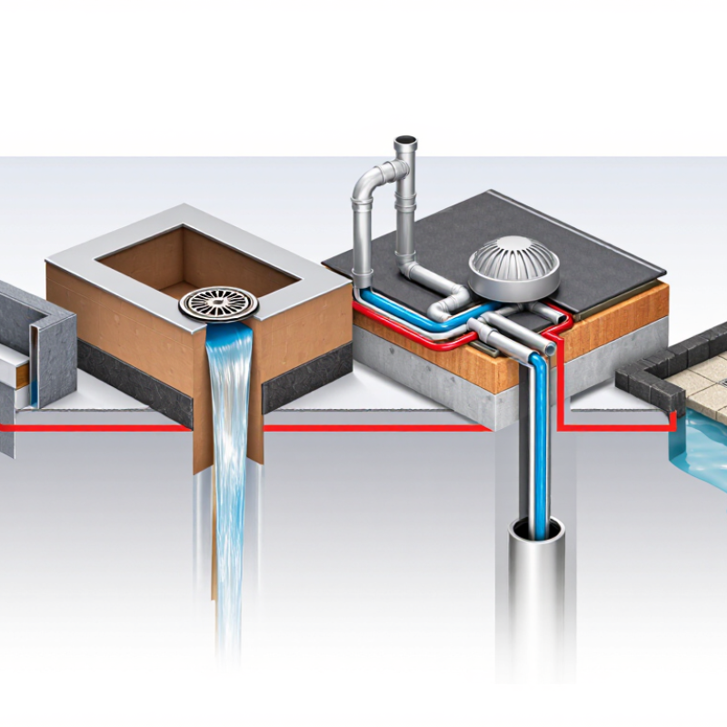
What Are the Top Types of Roof Drains?

Choosing the right Roof Drains is essential for protecting a building from ponding water, leaks, and structural damage. A flat commercial roof may appear quiet after rainfall, yet several inches of water can collect around blocked outlets. That hidden weight matters.

This guide examines the top types of roof drains, including interior drains, scupper drains, siphonic systems, and area drains. Each design manages water differently. Interior drains connect to concealed pipes beneath the roof surface. Scuppers direct water through parapet walls. Siphonic systems move large volumes quickly when properly engineered. Area drains often support smaller roof sections or terraces.

The best choice depends on roof slope, rainfall intensity, building use, and maintenance access. Experienced roofing professionals also inspect drain baskets, strainers, flashing, and nearby membrane seams. Small details often prevent expensive repairs. However, no drain type solves every drainage problem. That assumption can fail.

Local building codes and manufacturer instructions should guide final decisions. A qualified designer can calculate drainage capacity and emergency overflow requirements. Property owners should also consider seasonal debris, ice, and safe inspection routes. For example, leaves around a drain may look harmless in October but create standing water during a winter storm. This overview offers practical guidance, while site conditions still deserve careful evaluation. Good drainage is not only about moving water away. It is about keeping the roof dependable for years.

What Are the Top Types of Roof Drains?

Define Roof Drainage by Function, Flow Path, and Design Rainfall (IPC 2024)

What Are the Top Types of Roof Drains?

Define Roof Drainage by Function, Flow Path, and Design Rainfall (IPC 2024)

Roof drains are not interchangeable openings in a roof. Each type manages water differently. Internal drains collect runoff at low points and send it through vertical or horizontal piping. Scuppers discharge water through parapet walls, often into visible downspouts. Gutters collect edge runoff and direct it through leaders. The right choice depends on roof shape, structure, access, and local rainfall data.

Function comes first. A primary drain removes normal rainfall from the roof surface. An overflow drain or scupper provides a secondary path when the primary system blocks. This backup should remain visibly separate. A concealed overflow can delay warning signs and allow ponding to spread. It happens more often than designers expect.

Flow path and design rainfall determine pipe capacity under IPC 2024 requirements. Designers should use the jurisdiction’s adopted rainfall rate and the applicable drainage tables. They should also check roof area, slope, drain placement, leader size, and outlet restrictions. A drain that looks generous may still fail during a short, intense storm.

Field checks matter: leaves around a dome, a crushed leader, or standing water near a drain can reveal problems that drawings miss. Calculations guide the system. Site evidence tests it.

Internal Roof Drains for Low-Slope Roofs: Gravity Systems and Siphonic Options

Internal roof drains are a practical choice for low-slope roofs, where water cannot easily run to exterior eaves. They collect runoff through strainers, then move it through concealed piping. Gravity systems use natural slope and steady airflow. They are simple, familiar, and easier to inspect. Small details matter. A blocked strainer can leave water around rooftop equipment.

Drain capacity should follow local rainfall data, not guesswork. NOAA Atlas 14 precipitation-frequency estimates provide rainfall intensity for specific locations and return periods. Designers can use those values with roof area and pipe capacity calculations. FM Global Data Sheet 1-54 also emphasizes adequate drainage, overflow protection, and regular maintenance. The correct design depends on more than pipe diameter. Deck deflection, insulation layout, and outlet spacing can change the flow path.

Siphonic systems use specially designed outlets to limit air entry and create full-bore flow. This can move large volumes through smaller, more level pipes. It may reduce vertical penetrations and improve coordination in crowded buildings. Yet siphonic performance depends on accurate hydraulic modeling. Poor outlet placement can cause unstable flow, noise, or difficult maintenance. The Whole Building Design Guide notes that drainage design must coordinate structure, roofing, and mechanical systems. That coordination is often missed. Gravity drainage remains the safer choice for simpler roofs, while siphonic drainage can suit large footprints with consistent rainfall and careful engineering.

Siphonic Roof Drains: Full-Bore Flow and High-Capacity Design Principles

Roof drainage systems commonly use gravity drains, siphonic drains, and emergency overflow drains. Each type responds differently to rainfall intensity, roof shape, and pipe layout. Siphonic roof drains are designed for full-bore flow, allowing water to move through completely filled pipes.

Air matters. Special inlet components restrict air entry and help create negative pressure inside the system. This pressure difference can move water quickly across long horizontal runs. Compared with conventional gravity drainage, siphonic systems may require fewer outlets and smaller pipe diameters. However, capacity depends on accurate hydraulic calculations, not appearance.

Engineers must review roof levels, outlet locations, pipe slopes, and expected storm intensity. A flat roof with poorly positioned outlets can hold several centimeters of water after heavy rain. That added weight may affect structural performance. High-capacity design also requires secure supports, accessible inspection points, and properly sized emergency overflows. Field inspections often reveal blocked strainers, loose connections, or debris near inlets. These small defects can reduce performance significantly. Small errors matter.

Siphonic systems need careful coordination between structural, architectural, and mechanical teams. A pipe route that seems efficient may create difficult maintenance access. Designers should also consider partial-flow conditions during lighter rainfall, when siphonic action may not fully develop. This limitation is easy to overlook. Regular cleaning and post-storm checks remain important, even with a carefully engineered system.

What Are the Top Types of Roof Drains?

Siphonic Roof Drains: Full-Bore Flow and High-Capacity Design Principles

The chart compares the circular flow area of common nominal roof-drain outlet diameters. A larger outlet provides more potential flow area, while actual drainage capacity depends on rainfall intensity, hydraulic head, pipe length, friction, fittings, and whether the system operates by gravity or siphonic action.

Siphonic systems are designed to achieve full-bore flow by limiting air entry and using available roof-to-discharge elevation. The values shown are geometric flow areas calculated from A = π × (diameter ÷ 2)² and are not manufacturer-rated discharge capacities.

Scuppers and Overflow Scuppers: Open Discharge for Parapet Roofs (IBC)

Scuppers and overflow scuppers provide open drainage for parapet roofs, where roof edges are enclosed by raised walls. A primary scupper passes water through the parapet and releases it outside the building. Its outlet should project beyond the wall, preventing runoff from staining the façade or saturating masonry.

Overflow scuppers serve as visible emergency relief. They are normally positioned higher than the primary drainage openings. If leaves, ice, or a blocked drain raise the water level, the overflow opening discharges water before excessive ponding develops. Under the International Building Code, secondary drainage provisions may be required when blocked primary outlets could endanger the roof structure. Exact sizing, placement, and discharge paths depend on the adopted code and the building design.

A practical inspection should check the outlet slope, flashing, fasteners, and clear opening. Water should not spill onto a walkway, electrical equipment, or an adjacent lower roof. Splash blocks or approved extensions may control erosion at grade. The parapet cap also needs careful detailing around each penetration.

The arrangement is not flawless. Open outlets can freeze, clog, or discharge noisily during heavy rain. An overflow scupper can also reveal a blocked primary system, but only if someone notices it quickly. Drawings may show adequate drainage while field conditions reduce the opening. Roof debris, insulation thickness, and careless repairs deserve another look before approval. Local code officials and qualified roof professionals should verify the final design.

Gutters and Downspouts: Sizing by Roof Area and Rainfall Intensity (NRCA)

Roof drainage works only when gutters and downspouts match both roof area and rainfall intensity. A small roof can still overflow during a short, severe storm. The National Roofing Contractors Association recommends evaluating drainage capacity with local rainfall data, roof geometry, and site conditions. This approach is more reliable than copying a standard gutter size from another project.

Designers commonly estimate peak runoff with this formula: flow in gallons per minute equals roof area in square feet multiplied by rainfall intensity in inches per hour, divided by 96.3. For example, a 2,000-square-foot roof under a 4-inch-per-hour storm produces about 83 gallons per minute. The rainfall value should come from regional records, not guesswork. NOAA Atlas 14 provides precipitation-frequency estimates for many locations, including intense short-duration storms.

Downspout placement matters as much as gutter volume. Long gutter runs need more outlets, especially near valleys and inside corners. A clear 4-inch downspout may perform poorly when leaves, ice, or an undersized outlet restrict flow. Local plumbing standards also require specific sizing methods and overflow provisions. Field checks should include roof slope, gutter pitch, discharge location, and splashback near foundations. The calculation is useful, but it is not perfect. Climate records change, and unusual storms can exceed historical design values.

What Are the Top Types of Roof Drains? - Gutters and Downspouts: Sizing by Roof Area and Rainfall Intensity (NRCA)

Common Roof Drainage Types
Drainage Type Typical Roof Application Primary Water Path Key Sizing or Design Considerations Maintenance Focus
Gutters and Downspouts Sloped roofs and low-rise buildings with roof edges Gutter to outlet, then through a vertical or angled downspout Size according to contributing roof area, rainfall intensity, gutter slope, outlet capacity, and downspout capacity Remove leaves and sediment; inspect joints, hangers, outlets, and discharge points
Interior Roof Drains Low-slope roofs where piping can be routed inside the building Strainer and drain bowl connected to internal piping Provide adequate roof slope, drain spacing, pipe capacity, overflow drainage, and accessible cleanouts Keep strainers clear and inspect drain bowls, seals, piping, and overflow routes
Scuppers Low-slope roofs draining through parapet walls Roof surface through a wall opening to an exterior chute or conductor head Opening size, roof area, rainfall intensity, wall flashing, and unobstructed discharge must be evaluated Clear debris and verify that wall flashing, counterflashing, and exterior discharge remain open
Scuppers with Downspouts Parapet roofs where controlled exterior drainage is preferred Scupper through parapet, conductor head or outlet, then downspout The scupper, outlet, conductor head, and downspout must work as one continuous drainage system Inspect transitions for blockages, leakage, corrosion, and overflow staining
Siphonic Roof Drainage Large low-slope roofs requiring high-capacity drainage with minimal horizontal slope Specially designed outlets and pipework operating under full-bore flow conditions Requires hydraulic engineering, correctly designed outlets, pipe layout, air-entry control, and compatible structural support Use qualified inspection and verify outlets, pipe supports, and system performance
Emergency Overflow Drains or Scuppers Low-slope roofs with primary interior drains or concealed drainage paths Independent overflow route that releases water before excessive ponding develops Must be independent of the primary drainage path and positioned to provide visible warning of blocked primary drains Keep openings visible and unobstructed; inspect after severe storms
Example Gutter and Downspout Flow Calculations
Contributing Roof Area Rainfall Intensity Runoff Coefficient Estimated Design Flow Planning Interpretation
1,000 sq. ft. 2 in./hr. 1.0 20.8 gal./min. Small roof section; verify the selected gutter outlet and downspout can carry at least this flow
1,500 sq. ft. 3 in./hr. 1.0 46.9 gal./min. Moderate roof section; additional outlets may be needed where flow is divided between drainage points
2,000 sq. ft. 4 in./hr. 1.0 83.3 gal./min. Large roof section; use a coordinated gutter, outlet, downspout, and discharge design
2,500 sq. ft. 5 in./hr. 1.0 130.2 gal./min. High design flow; divide the drainage area or use an engineered high-capacity system
Calculation reference: Estimated flow in gallons per minute is calculated using Q = C × i × A ÷ 96, where Q is flow in gallons per minute, C is the runoff coefficient, i is rainfall intensity in inches per hour, and A is contributing roof area in square feet. The examples use C = 1.0 for a simplified impervious-roof calculation. Final gutter, downspout, roof-drain, overflow, and scupper dimensions should be verified using local code requirements, project-specific rainfall data, roof geometry, and hydraulic capacity data.
Top