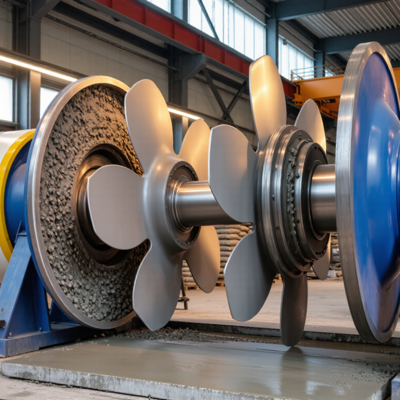
| Mixer Type | Horizontal twin-shaft forced-action concrete mixer | Two counter-rotating shafts actively move the materials instead of relying mainly on gravity. |
| Main Mixing Principle | Convection, shearing, lifting, folding, and cross-mixing | These combined actions distribute cement paste, water, aggregates, and admixtures throughout the batch. |
| Number of Shafts | Two parallel horizontal shafts | The shafts create two interacting mixing zones and improve material circulation across the chamber. |
| Shaft Rotation | Counter-rotation; the exact direction depends on the mixer design | Opposing movement helps generate turbulence and transfers material between the two shafts. |
| Mixing Paddles | Wear-resistant paddles mounted around each shaft | Paddles lift, push, split, and fold the mixture while maintaining continuous contact with the batch. |
| Paddle Arrangement | Helical or staggered arrangement with adjustable overlap and angle | The arrangement controls axial movement, mixing intensity, and the time required to reach uniformity. |
| Typical Effective Fill Level | Approximately 50%–70% of the effective mixing volume, depending on the material and design | Correct filling allows the paddles to circulate the batch without excessive dead zones or overload. |
| Common Nominal Batch Sizes | Approximately 0.5–6.0 m³ per batch for common construction applications | The required size depends on plant output, concrete type, cycle time, and available installation space. |
| Typical Mixing Time | About 30–90 seconds after all major ingredients enter the chamber | Actual time varies with moisture, aggregate grading, recipe complexity, batch size, and discharge requirements. |
| Typical Rotor Speed | Commonly about 15–35 revolutions per minute | Lower speeds handle dense concrete efficiently, while the selected speed must limit splashing, segregation, and wear. |
| Material Compatibility | Normal concrete, high-strength concrete, dry concrete, mortars, and many low-slump mixes | Forced mixing is useful when the mix contains coarse aggregates, limited water, fibers, or supplementary cementitious materials. |
| Aggregate Size | Often suitable for aggregate sizes up to approximately 40–80 mm, subject to mixer design | The permitted maximum size is determined by paddle clearance, chamber geometry, and the manufacturer’s engineering limits. |
| Paddle-to-Liner Clearance | Usually kept small and checked during maintenance; the exact value is design-specific | Proper clearance promotes effective scraping and mixing while preventing contact between rotating paddles and liners. |
| Mixing Chamber | Horizontal trough with replaceable wear liners | The chamber contains the material, while replaceable liners protect the shell from abrasive aggregates and cement paste. |
| Drive System | Electric motors, reduction gearboxes, couplings, and synchronized shaft transmission | The drive must deliver high torque at low speed and keep both shafts synchronized under changing loads. |
| Discharge Method | Hydraulic, pneumatic, or mechanically actuated bottom discharge gate | A wide discharge opening helps empty the chamber quickly and reduces leftover concrete between batches. |
| Uniformity Indicator | Consistent color, moisture distribution, aggregate dispersion, and slump throughout the batch | Uniformity should be verified through production testing rather than judged only by mixing time. |
| Key Advantages | Fast mixing, strong homogenization, good low-slump performance, and efficient fiber dispersion | The interaction between the two shafts and paddles exposes more material to active mixing forces. |
| Main Maintenance Points | Paddles, liners, shaft seals, bearings, gearboxes, discharge gates, and lubrication points | Routine inspection helps maintain mixing quality, prevent leakage, and reduce unplanned downtime. |