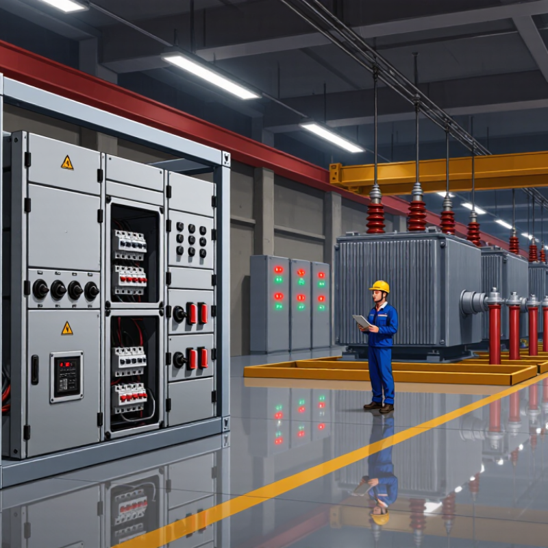
| Incoming supply | Incoming circuit breaker and protection relays | Common sub-transmission and transmission levels include 33 kV, 66 kV, 132 kV, and higher, depending on the network. | Connects the incoming circuit to the substation bus and interrupts current when a detected fault meets the protection settings. | Helps isolate faults and allows the transformer circuit to be disconnected for maintenance. |
| Substation bus | Busbars, bus couplers, and associated switching devices | Voltage depends on the substation design; distribution substations commonly use medium-voltage buses such as 11 kV or 33 kV. | Provides a shared electrical connection between incoming circuits, transformer bays, and outgoing feeders. | Enables controlled switching and can provide alternative supply paths where the network design allows. |
| Transformer high-voltage side | Circuit breaker or other specified switching and protection arrangement | Selected to match the transformer winding and system voltage, for example 33 kV or 132 kV. | Controls and protects the transformer’s high-voltage connection; the exact arrangement depends on the system and transformer design. | Supports safe fault clearing and helps limit the impact of a transformer or connected-circuit fault. |
| Transformer | Power transformer (connected between switchgear sections) | Changes voltage between system levels, such as 132 kV to 33 kV or 33 kV to 11 kV; actual ratios vary by network. | Transfers electrical power between windings by electromagnetic induction and changes the voltage level. | Makes power suitable for onward transmission, distribution, or use by connected loads. |
| Transformer low-voltage side | Low-voltage or medium-voltage circuit breaker and protection | Common distribution outputs include 11 kV or 33 kV; local Distribution Transformers may supply 400/230 V in many systems. | Connects the transformer output to a downstream bus or feeder and provides switching and fault protection. | Allows downstream circuits to be isolated without necessarily disconnecting every other circuit on the network. |
| Outgoing distribution circuits | Feeder circuit breakers, fuses, or switch-fuse units, as appropriate | Distribution feeders commonly operate at medium voltage, such as 11 kV or 33 kV, or at low voltage near end users. | Routes power from the substation to other substations, distribution transformers, or loads. | Selective protection can disconnect an affected feeder while helping keep healthy parts of the system in service. |
| Isolation and safe access | Disconnectors, earthing switches, and interlocking arrangements | Selected for the circuit’s rated voltage and the applicable operating and safety requirements. | Provides isolation and, where designed for it, earthing of equipment during approved maintenance procedures. A disconnector is generally not intended to interrupt normal load current. | Helps establish a safe work condition when operated according to procedures and verified isolation requirements. |
| Protection and monitoring | Current transformers, voltage transformers, and protective relays | Instrument-transformer ratios and relay settings are engineered for the specific voltage, current, and protection scheme. | Supply measurement signals to protection and control equipment, which can command a circuit breaker to trip when specified conditions occur. | Enables fault detection and coordinated protection; settings must be designed and tested for the particular power system. |