What Are the Top Water Diaphragm Valve Types in 2026?
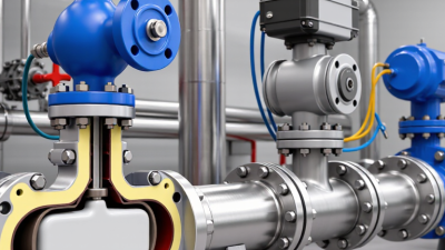
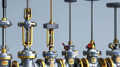
In 2026, selecting a water diaphragm valve means matching its design to the actual service, not simply choosing the most popular option. Weir-type valves are common where controlled shutoff and a relatively shallow flow path matter. Straight-through designs can suit applications that need a less obstructed passage, though their installation space and operating requirements should be checked carefully. There is no universal winner.
This guide compares the main valve types and explains where each may fit. It also looks at manual and actuated operation, body and diaphragm materials, pressure limits, and maintenance access. A valve used in a treatment line may face different demands from one installed near a pump or storage tank. Small details count. A tight installation, abrasive particles, or frequent cycling can change which design is practical.
Reliable selection starts with verified specifications. Check the manufacturer’s pressure and temperature ratings, connection dimensions, material compatibility, and any required approvals for the intended water service. Product descriptions can make similar valves sound interchangeable; they are not always so. Even a sound recommendation has limits when operating data is missing. Use this overview to narrow the options, then confirm the final choice against project conditions and current product documentation.
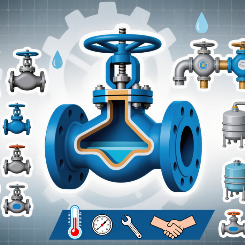
How Water Diaphragm Valves Work: ISO 5208 Pressure-Test Methods
For water diaphragm valves, pressure testing checks two distinct risks: leakage through the body and leakage across the closed diaphragm. ISO 5208:2015 specifies pressure-test procedures and leakage-rate criteria for industrial valves. Its standard test pressures are generally 1.5 times the maximum allowable pressure for shell testing and 1.1 times for closure testing, referenced to 20°C. The applicable product specification and test plan still matter; these figures should not replace them. Under Rate A, no visible leakage is permitted during the specified test.
In practice, a technician fills the valve with test liquid, removes trapped air, and raises pressure gradually. They inspect the body, joints, and diaphragm area, then record pressure, duration, and observed leakage. A dry exterior does not prove the closed valve seals correctly, so shell and closure results should be documented separately. For water service, this distinction helps identify whether a fault lies in the pressure boundary or the shutoff function. Test duration and acceptance criteria can vary with valve size and specification.
Tips: Confirm the test medium, pressure, hold time, and leakage class before testing. Photographing the gauge and valve condition can improve traceability. ISO 5208 provides a repeatable framework, but field conditions are imperfect; temperature changes or trapped air can distort readings. નોંધ
Weir-Type Valves for Clean Water: Control and Shutoff Uses
For clean-water service, a weir-type diaphragm valve can provide both flow adjustment and shutoff in one compact body.
A raised section, or weir, crosses the flow path. The flexible diaphragm presses against it to close the passage. Because the wetted path is relatively simple, inspection and cleaning can be manageable.
A practical detail matters.
In a treatment room or building service line, an operator might partly open the valve to adjust flow through a branch, then close it for maintenance. The result depends on valve size, pressure drop, and diaphragm material.
It is not automatically a precision control valve.
For frequent throttling, check the specified operating range and watch for vibration or uneven diaphragm wear. Water clarity alone is not enough when selecting materials; disinfectants, temperature, and cleaning methods also affect compatibility.
For shutoff, confirm the pressure rating and test performance under expected site conditions. A fully turned handwheel does not, by itself, prove leak-tight closure.
Not automatically.
Diaphragms are service parts, so access and replacement intervals deserve attention during planning. A spare diaphragm may reduce downtime, but replacement still requires isolation and careful reassembly.
Slightly inconvenient, perhaps, but worth accounting for before installation.
Straight-Through Valves for Slurry: Full-Bore Flow-Path Design
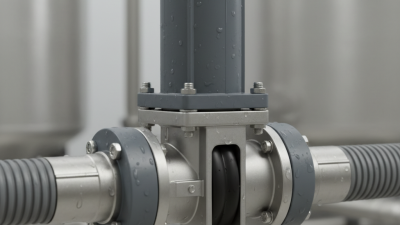
For slurry duty, a straight-through diaphragm valve keeps the flow path comparatively open, without the raised weir found in many designs. Its full-bore geometry can reduce abrupt changes in direction, helping coarse particles pass with less obstruction. That matters. In a process line carrying mineral slurry, a narrow passage can collect solids during low-flow periods and complicate flushing.
The open path does not prevent wear. Abrasive particles can still erode the body, lining, or diaphragm, especially near bends and throttling points. Match wetted materials to the slurry’s chemistry, particle size, temperature, and operating pressure. A practical check is to compare the valve’s stated bore with the pipe bore, then inspect the diaphragm for cuts or uneven wear during planned maintenance. Watch for settling, too. A full-bore valve may still plug if solids sit in the line while flow stops. It is not a cure-all. Operators sometimes assume the largest passage always performs best, but control needs, closure frequency, and available maintenance access also shape the choice. A short trial under representative flow conditions can reveal issues that a drawing will miss.
EPDM, NBR, and PTFE Diaphragms: Compare Media and Temperature Limits
For water diaphragm valves, material choice affects sealing, service life, and temperature tolerance. EPDM is a common option for clean water and many hot-water applications. Typical operating limits are about -40°C to 120°C, though some compounds allow brief excursions beyond this range. It suits water well, but oils and many hydrocarbon fluids can cause swelling. Check the actual water chemistry, too.
NBR is often selected where water may contain traces of oil or grease. Its typical range is roughly -20°C to 100°C, with heat and chemical compatibility varying by compound. It is generally less suitable than EPDM for sustained hot-water service. A small temperature difference can matter over months of repeated cycles. That detail is easy to overlook.
PTFE offers broad chemical resistance and can often tolerate higher temperatures, commonly around -20°C to 180°C in valve designs. The valve’s construction may impose a lower limit than the PTFE itself. PTFE is also less elastic than rubber, so some diaphragms use an elastomer backing for sealing and flex support. Not a perfect fit for every duty. Before choosing, compare the manufacturer’s temperature rating with pressure, cleaning chemicals, and cycling frequency; published ranges are guides, not guarantees.
What Are the Top Water Diaphragm Valve Types in 2026? — EPDM, NBR, and PTFE Diaphragms: Compare Media and Temperature Limits
| Diaphragm Material |
Typical Temperature Range* |
Water and Media Compatibility |
Key Advantages |
Important Limitations |
Common Water-Service Uses |
| EPDM |
Approximately −40°C to +120°C (−40°F to +248°F) |
Generally well suited to water, hot water, and many dilute aqueous solutions. Often selected for water service where resistance to weathering and ozone is useful. |
Good flexibility and resilience; typically performs well in hot-water service and outdoor environments. |
Generally unsuitable for petroleum oils, fuels, and many hydrocarbon-based fluids. Compatibility depends on the specific compound and water chemistry. |
General water distribution, hot-water systems, and water-treatment lines, subject to the valve and compound rating. |
| NBR (Buna-N) |
Approximately −20°C to +80°C (−4°F to +176°F) for many water-service compounds; some formulations have different limits. |
Often a suitable choice where water service also involves oils or grease. Compatibility with hot water and additives should be checked carefully. |
Good resistance to many petroleum oils and greases; can be a practical option for mixed water-and-oil service. |
Usually less suitable than EPDM for sustained hot-water service. Heat, ozone, and weather resistance vary by formulation. Potable-water use requires the appropriate material approval. |
Cool or moderate-temperature water systems where oil resistance is needed, such as some industrial utility lines. |
| PTFE |
Many diaphragm-valve designs are rated for approximately −20°C to +150°C (−4°F to +302°F); the complete valve assembly may have a lower limit. |
Very broad chemical resistance in aqueous service, including many acids, alkalis, and process-water chemicals. Verify compatibility with the specific chemical mixture. |
Excellent chemical resistance and low water absorption; useful where elastomer compatibility is a concern. |
Less elastic than rubber diaphragms and can require an elastomer backing layer for flexibility and sealing. Repeated flexing, pressure, and temperature limits depend on diaphragm construction. |
Chemically demanding water-treatment and process-water applications where the fluid is compatible with the valve body and other wetted parts. |
Selection note: Temperature ranges are general reference values, not universal ratings. Actual limits depend on the diaphragm compound, construction, pressure, valve body, and operating cycle. Check the complete valve’s published limits and verify potable-water approvals where required.