Why Use a Motorized Valve in Industrial Systems?

Industrial systems must control fluids accurately, safely, and repeatedly. A motorized valve provides this control by opening or closing through an electric actuator. It can manage water, steam, compressed air, chemicals, and process fluids. Operators can adjust flow without standing beside hot pipes or enclosed equipment.

In practical installations, the benefits become visible during routine operation. A control room can open a valve while monitoring pressure, temperature, and flow. This reduces manual intervention and supports consistent production. Motorized valve systems also connect with PLCs, SCADA platforms, and building management controls. Engineers can program timed movements, emergency shutoff responses, and gradual flow adjustments. These functions may reduce process variation and improve workplace safety when properly designed.

However, motorized valves are not automatically the best choice. Wrong actuator sizing can cause slow movement, overheating, or incomplete closure. Poor wiring creates another failure point. Dust, moisture, vibration, and corrosive media also demand careful component selection. I have seen reliable systems underperform because maintenance teams ignored torque requirements or position feedback. That lesson is easy to overlook.

Good engineering begins with the process conditions. Designers should verify pressure ratings, temperature limits, flow requirements, valve materials, actuator torque, and fail-safe behavior. Relevant manufacturer data and recognized industrial standards should guide selection. Regular inspection remains essential, even when automation appears dependable. A motorized valve can improve control and reliability, but only when installation, commissioning, and maintenance receive equal attention. Sometimes, a simpler manual valve remains more practical. Context matters.

Why Use a Motorized Valve in Industrial Systems?

What Is a Motorized Valve?

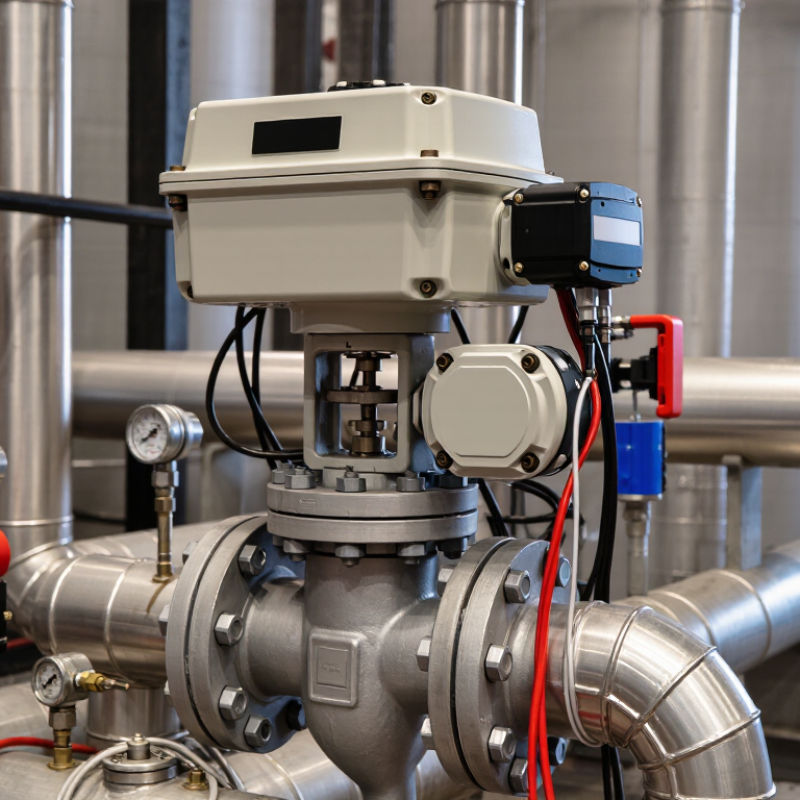
A motorized valve is a flow-control device operated by an electric actuator. The actuator converts electrical energy into rotary or linear movement. That movement opens, closes, or positions the valve. A controller can send a timed, proportional, or emergency signal. This allows operators to manage water, steam, compressed air, fuel, or chemicals from a control room.

It is not simply an automatic valve. The system usually includes a valve body, actuator, limit switches, feedback sensors, and control wiring. For example, a partially open valve can maintain a stable cooling-water temperature near a heat exchanger. A fully closed valve can isolate a pipeline during maintenance. The U.S. Department of Energy estimates that pumping systems consume about 27% of industrial electricity in the United States. Better valve positioning can reduce unnecessary flow resistance, although poor sizing may increase energy use. That detail is often missed.

The International Energy Agency reported that industry used roughly 37% of global final energy in 2022. This makes reliable flow control more important. In practice, engineers check torque, pressure rating, duty cycle, response time, and failure position before selection. A valve that works well in a clean-water test may perform poorly with hot slurry. That is a real limitation. Feedback also matters. Without position feedback, a controller may assume movement occurred when the valve is stuck. Operators should verify actual travel, leakage, and maintenance access during commissioning.

How Motorized Valves Operate in Industrial Systems

Why Use a Motorized Valve in Industrial Systems?

How Motorized Valves Operate in Industrial Systems

In industrial systems, a motorized valve changes fluid flow without constant manual operation. An electric actuator receives a command from a PLC, control panel, or process sensor. The actuator converts electrical energy into controlled rotary or linear movement. A gearbox increases torque when the valve requires more force. The stem then opens, closes, or positions the valve. Small movements matter. They can stabilize pressure, temperature, or tank level.

During operation, limit switches identify fully open and closed positions. Position feedback can also report intermediate movement to the control system. This lets operators compare the requested position with the actual position. If the values differ, the system can trigger an alarm or stop the actuator. In many plants, technicians test these signals during commissioning. They also inspect wiring, torque settings, and mechanical alignment. A poorly aligned stem may create resistance, heat, and premature wear.

The correct operating method depends on the process and valve design. Some systems use on-off control, while others require precise modulating control. A power-loss response must be selected carefully. The valve may remain in place, close, or open through a separate backup arrangement. This choice affects safety and process stability. One detail is often missed: feedback does not prove the valve is sealing. Periodic inspection remains necessary. Motorized control reduces routine labor, but it does not replace engineering judgment.

Key Benefits of Using Motorized Valves

Motorized valves give industrial systems precise flow control without requiring an operator to reach every pipe. A signal can close a valve within seconds during a pressure spike. That matters near hot steam lines, chemical dosing points, and elevated tanks. In field inspections, remote positioning also reduces repeated manual adjustments and improves process consistency. Small gains, repeated daily.

The energy case is indirect, but important. The U.S. Department of Energy reports that motor-driven equipment uses more than half of industrial electricity, making efficient control a practical concern (DOE, Improving Motor and Drive System Performance, 2022). A motorized valve can prevent over-pumping, bypass losses, and unnecessary circulation when linked to sensors and variable-speed equipment. The International Energy Agency identifies industrial energy efficiency as a major emissions-reduction opportunity (IEA, Energy Efficiency 2023). Automation supports that effort, though it does not guarantee savings. Poor sizing can waste power.

Maintenance benefits are equally tangible. Position feedback can reveal a stuck valve before a tank overflows. Scheduled operation can limit water hammer and reduce sudden pressure changes. Digital records also help technicians compare commanded and actual positions. Yet feedback is not perfection. Sensors drift, wiring fails, and a “smart” valve still needs inspection, testing, and a safe manual override. Reliability improves when engineers specify fail-safe behavior, ingress protection, torque margins, and accessible service points from the start.

Common Industrial Applications

Motorized valves are common in industrial systems because they regulate fluid flow without constant manual operation.

An electric actuator turns the valve in response to a control signal. This helps operators manage water, steam, air, fuel, and process liquids from a safe location. In busy plants, precise movement can reduce sudden pressure changes and unnecessary energy use.

Water and wastewater facilities use motorized valves for filtration, pumping, chemical dosing, and storage tanks. Operators can isolate a pipeline before maintenance or adjust flow during changing demand. In chemical processing, these valves control corrosive liquids and heated mixtures inside enclosed pipe networks. Correct material selection matters. A small compatibility mistake may cause leakage, early wear, or an unsafe shutdown.

Heating, ventilation, and cooling systems use them to balance chilled water, hot water, and steam. Manufacturing plants also install motorized valves on compressed-air lines, cooling circuits, and production equipment. Food-processing facilities need cleanable designs and reliable position feedback. Energy plants often use them around boilers, condensers, and cooling towers.

Field experience shows that installation details matter as much as the valve itself. Poor wiring, moisture, or incorrect actuator sizing can create repeated faults. Engineers should check operating temperature, pressure, cycle frequency, emergency position, and maintenance access before approval. Sometimes, a simpler manual valve is still more practical for a rarely used line.

Factors to Consider When Selecting a Motorized Valve

Why Use a Motorized Valve in Industrial Systems?

Factors to Consider When Selecting a Motorized Valve

When selecting a motorized valve, match it to the process, not just the pipe size. The right choice can regulate flow, isolate equipment, and reduce manual work in difficult areas. Start with the fluid, temperature, pressure, and flow rate. Water, steam, chemicals, and abrasive slurries place very different demands on valve materials and seals. A valve handling hot water may need stainless steel components and high-temperature sealing.

Do not ignore actuator details. Torque matters. Choose an actuator with enough capacity to overcome pressure, friction, and occasional deposits inside the valve. Check the required control signal, such as a simple on/off command or a 4–20 mA position signal. Power supply, operating speed, duty cycle, enclosure rating, and manual override also affect dependable operation. In a humid pump room, for example, poor enclosure protection can cause early electrical failure.

Consider the failure position carefully. A cooling line may need to open during a power loss, while a fuel isolation line may need to close. The answer depends on the process risk and the site’s safety procedures. Installation space and future maintenance deserve attention too. Keep it accessible. I have seen well-sized valves installed behind fixed panels, making routine inspection unnecessarily difficult. A clean specification sheet does not guarantee a practical installation. Review compatibility, testing records, spare parts, and expected service life with qualified technicians before approval.

Why Use a Motorized Valve in Industrial Systems? - Factors to Consider When Selecting a Motorized Valve

Selection Factor Typical Data or Range What to Consider Industrial Value
Valve Function On/off isolation, diverting, mixing, or modulating control Choose a valve body and actuator combination that matches the required control duty. Quarter-turn ball and butterfly valves are commonly used for isolation, while globe valves are often selected for more precise throttling. Provides automated flow isolation or regulation without continuous manual intervention.
Flow Medium Water, air, steam, oil, chemicals, gases, or abrasive slurries Check chemical compatibility, viscosity, solids content, cleanliness, and corrosion risk. The seat, seals, body, and stem materials must be suitable for the medium. Reduces leakage, premature wear, contamination, and unplanned replacement.
Nominal Size Common industrial sizes range from DN15 to DN600 or larger Size the valve according to required flow, pressure drop, pipe size, and available installation space. A valve should not be selected solely by matching the pipe diameter. Supports efficient flow control while avoiding excessive pressure loss and actuator overload.
Pressure Rating Common ratings include PN10, PN16, PN25, Class 150, and higher The pressure rating must exceed the maximum operating pressure, including surge or water-hammer conditions. Consider pressure-temperature derating where applicable. Improves operating safety and reduces the risk of body, seat, or connection failure.
Temperature Range Approximately -20°C to 180°C for many general-purpose assemblies; specialized designs cover wider ranges Evaluate normal, minimum, and maximum process temperatures. High-temperature service may require metal seats, heat-resistant seals, actuator separation, or special insulation. Maintains sealing performance and actuator reliability under changing process conditions.
Actuator Torque or Thrust Must exceed the valve breakaway and running torque or required linear thrust, with a safety margin Account for differential pressure, seat friction, scaling, corrosion, low-temperature effects, and emergency operating conditions. The actuator should not be under-sized or unnecessarily oversized. Ensures dependable opening and closing while limiting energy consumption and mechanical stress.
Control Signal Digital on/off, 24 V AC/DC, 110–120 V AC, 220–240 V AC, 4–20 mA, or fieldbus communication Match the actuator input and feedback signals with the plant control system, PLC, DCS, or building management system. Verify signal isolation and wiring requirements. Enables centralized control, remote monitoring, sequencing, and process automation.
Position Feedback Open/closed limit switches, potentiometer feedback, or continuous 4–20 mA position feedback Use simple limit switches for basic isolation. Select continuous feedback when the control system must verify actual valve position or manage proportional flow. Improves diagnostics, interlocking, alarm management, and process visibility.
Fail-Safe Requirement Fail-open, fail-closed, or fail-in-place operation during power loss Determine the safe position from the process hazard analysis. Electric actuators may require a spring-return mechanism, battery backup, or an uninterruptible power supply for fail-safe operation. Helps protect personnel, equipment, and the process during power or control-system failures.
Operating Speed Typical quarter-turn electric actuators operate in approximately 10–120 seconds Select the speed according to process requirements. Excessively fast closure can cause water hammer, pressure shock, or mechanical impact in liquid systems. Balances responsive automation with stable and safe process operation.
Ingress Protection IP65, IP66, or IP67 are common choices for protected industrial installations Choose the enclosure rating according to dust, water spray, washdown, outdoor exposure, and temporary immersion risks. Hazardous areas may require certified explosion-protected equipment. Protects electrical components from moisture, dust, and environmental damage.
Duty Cycle Intermittent duty is common; frequent cycling requires a suitable motor and thermal rating Estimate cycles per hour, operation time, stall conditions, and seasonal demand. Do not use an actuator designed for occasional isolation in high-frequency modulating service. Extends service life and prevents overheating or premature actuator failure.
Power Supply 24 V DC, 24 V AC, 110–120 V AC, or 220–240 V AC are widely used Confirm voltage, frequency, starting current, cable length, voltage drop, and available backup power. Low-voltage systems may improve electrical safety but can require higher current. Ensures reliable operation and simplifies integration with the existing electrical infrastructure.
Leakage and Shutoff Class Select the required seat leakage level based on the application and valve standard Tight shutoff is important for isolation, while controlled leakage may be acceptable in some regulation services. Verify the applicable testing standard and pressure differential. Limits product loss, cross-contamination, emissions, and safety risks during isolation.
Installation and Maintenance Consider orientation, accessibility, manual override, replaceable seals, and service clearance Provide adequate access for inspection and actuator removal. A manual override can be useful during commissioning or power loss, but it should not create an unintended safety hazard. Reduces downtime and makes troubleshooting, testing, and preventive maintenance easier.
Total Cost of Ownership Purchase cost plus installation, energy use, calibration, maintenance, downtime, and replacement Compare the complete lifecycle cost rather than the initial purchase price. Consider cycle frequency, spare parts, service intervals, energy consumption, and expected operating life. Supports better investment decisions and can reduce long-term operating expenses.

Note: The stated ranges are general engineering references. Final valve and actuator selection should be verified against the process design, applicable standards, manufacturer sizing data, and site safety requirements.

Top