Top Motorized Valve Types and How to Choose

A motorized valve turns an electrical or pneumatic command into controlled movement inside a pipe system. That movement may start, stop, or regulate water, air, steam, or another compatible fluid. Small details matter. A valve that looks suitable on a product page may not fit the pipe size, pressure range, temperature, or control signal in the actual installation.

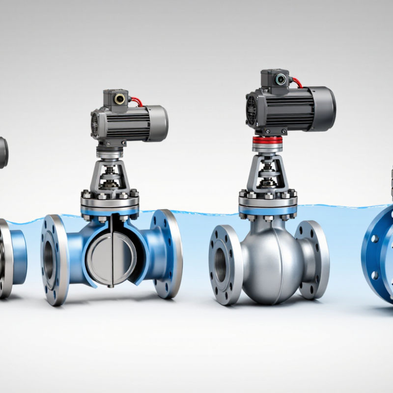
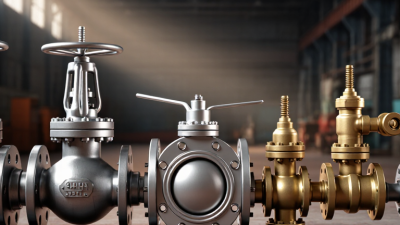
Common options include ball, butterfly, globe, and gate valves, each with different strengths. Ball valves often provide quick shutoff and a tight seal, while butterfly valves can be compact in larger lines. Globe valves are commonly considered when throttling control matters. Gate valves generally suit on-off service better than frequent flow adjustment. These are useful starting points, not universal rules. Not always. Actual performance depends on materials, actuator torque, fluid conditions, and how often the valve operates.

Choosing a motorized valve means matching the valve body and actuator to the job. Check connection type, voltage, control method, fail position, response time, and maintenance access. For example, a valve mounted behind a panel may be difficult to inspect, even if its specifications look ideal. Confirming operating conditions with the system designer or manufacturer can prevent avoidable sizing errors. Selection is rarely perfect from a checklist alone; field conditions can surprise you. This guide compares major valve types and explains practical selection factors, so readers can narrow options with clearer evidence and fewer assumptions.

Top Motorized Valve Types and How to Choose

What Motorized Valves Are and How They Operate

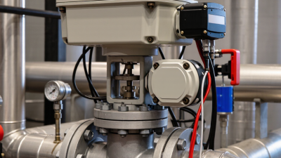
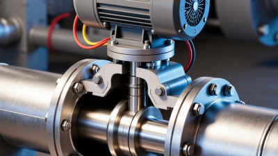
A motorized valve combines a valve body with an electric actuator. The actuator converts electrical energy into rotation or linear movement, shifting a ball, disc, plug, or stem. A controller may command fully open, fully closed, or an intermediate position. Simple systems use on/off signals; modulating systems adjust position to manage flow or pressure.

Inside the actuator, a motor and gear train deliver the torque needed to move the valve. Position sensors can report whether it reached the requested setting. The U.S. Department of Energy’s Improving Motor and Drive System Performance: A Sourcebook for Industry notes that motor-driven systems use about 70% of electricity in U.S. manufacturing. That figure covers many machines, not valves alone, but it shows why efficient motor control matters. Small adjustments count.

Selection depends on more than pipe size. Engineers check fluid type, operating temperature, pressure difference, required torque, cycle frequency, and control signal. A valve that works smoothly with water may struggle with thicker fluids or frequent cycling. In practice, actuator sizing can look tidy on paper, yet installation friction and changing pressure complicate it. Worth checking twice. Power-loss behavior also matters: an electric actuator may stay in place unless it includes a spring return or backup power.

Common Types of Motorized Valves and Their Uses

Top Motorized Valve Types and How to Choose
Common Types of Motorized Valves and Their Uses

Motorized ball valves use a quarter-turn motion to open or close flow. They suit water lines, heating circuits, and other services where dependable shutoff matters more than fine flow adjustment. Compact and quick. Check the valve’s pressure rating and actuator torque, especially when the line may contain debris or scale.

Butterfly valves are common in larger pipes, such as building HVAC and water distribution systems. Their light, compact design can make installation easier, though they may not provide the tightest shutoff in every application. Globe valves move a plug along a linear path, allowing more controlled throttling. They are useful where flow needs frequent adjustment, but pressure loss can be higher.

Diaphragm valves separate the moving parts from the process fluid, making them useful for some corrosive, dirty, or hygienic services. Not always ideal. Material compatibility still needs careful checking. Match the valve body and seal materials to the fluid, temperature, and pressure. Then consider control needs, available power, operating frequency, and the required position during a power failure. A valve selected only by pipe size can disappoint; actual flow conditions matter too.

Top Motorized Valve Types and How to Choose

Typical travel for quarter-turn valves: Motorized ball, butterfly, and plug valves generally rotate 90° between fully open and fully closed. Choose among them based on pressure, flow capacity, shutoff requirements, and available space. Motorized gate and globe valves use linear or multi-turn movement, so their travel varies by valve design and size.

Key Differences Between Valve Designs and Actuators

A motorized valve is a pairing: the valve controls flow, while the actuator supplies motion. Ball and butterfly valves turn a quarter-turn, making them compact choices for on-off service. Globe valves move linearly and generally offer finer throttling. Gate valves suit isolation, but are poor candidates for frequent flow adjustment. Small details matter.

Actuator choice changes the response. Electric actuators can provide repeatable positioning and avoid plant air lines. Pneumatic actuators often respond quickly and can spring to a chosen safe position during air loss. Hydraulic units deliver high force, but need more supporting equipment. The U.S. Department of Energy’s Improving Motor and Drive System Performance sourcebook reports that motor-driven systems use about 68% of U.S. manufacturing electricity. That figure covers entire motor systems, not valve actuators alone; still, actuator duty and control strategy deserve an energy review.

Match the actuator to the valve’s actual torque or thrust needs, including differential pressure, temperature, seat friction, and cycling frequency. IEC 60534-2-1 provides standardized methods for sizing control valves; sizing the valve alone does not size its actuator. In field selection, engineers should also check signal type, enclosure rating, stroke time, and failure behavior. A common mistake is choosing from nominal pipe size alone. It seems convenient, but it can leave the actuator undersized when pressure conditions change.

Top Motorized Valve Types and How to Choose — Key Differences Between Valve Designs and Actuators
Valve Type Motion and Typical Actuation Flow Control and Shutoff Key Advantages Limitations and Selection Notes Common Applications
Ball valve Quarter-turn; commonly paired with an electric or pneumatic rotary actuator. Generally suited to on/off service; characterized-port designs can provide modulating control. Often offers tight shutoff. Fast operation, compact construction, and relatively low pressure drop when fully open. Standard full-port designs are not automatically suitable for precise throttling. Confirm seat material, pressure and temperature limits, and required torque. Process isolation, water systems, compressed air, and compatible gas or liquid services.
Butterfly valve Quarter-turn; commonly paired with an electric or pneumatic rotary actuator. Used for on/off service and, with an appropriate disc and actuator, flow modulation. Lightweight and compact, especially in larger pipe sizes; typically requires less space than many multi-turn valve arrangements. The disc remains in the flow path, creating some obstruction. Performance depends on seat design, pressure, temperature, and fluid compatibility. Water distribution, HVAC, cooling-water circuits, and many low- to moderate-pressure services.
Gate valve Linear, multi-turn; typically uses an electric multi-turn actuator or a linear actuator arrangement. Primarily for fully open or fully closed service; generally not recommended for sustained throttling. When fully open, it provides a relatively unobstructed flow path and low flow resistance. Slower to operate than quarter-turn designs. Requires more installation height, and prolonged throttling can damage internal components. Isolation in pipelines, utility systems, and services where infrequent operation is expected.
Globe valve Linear; commonly paired with an electric or pneumatic linear actuator. Well suited to throttling and regulating flow; shutoff performance depends on the design and service conditions. Offers controllable flow adjustment and is commonly used where regulation is more important than minimum pressure loss. Typically has greater pressure drop than a straight-through gate valve. Actuator thrust and valve sizing should account for differential pressure. Control loops, steam and process services, and systems requiring frequent flow adjustment.
Plug valve Usually quarter-turn; commonly paired with an electric or pneumatic rotary actuator. Often used for on/off isolation; some designs are suitable for throttling or diverting flow. Simple rotary operation; multiport versions can direct flow between different ports. Operating torque can be significant, particularly with some lubricated or tight-sealing designs. Check fluid compatibility and maintenance needs. Process isolation, diversion, and certain slurry or utility services, depending on construction.
Diaphragm valve Linear; commonly paired with a pneumatic diaphragm actuator or an electric linear actuator. Can provide shutoff and flow regulation; the diaphragm separates the process fluid from the operating mechanism. Useful for corrosive, contaminated, or hygienic services when body and diaphragm materials are appropriately selected. Diaphragm material and pressure-temperature limits constrain service suitability. It is generally not intended for every high-pressure application. Water treatment, chemical dosing, pharmaceutical processes, and other services requiring fluid isolation from the stem area.
How to choose an actuator: Select rotary actuation for quarter-turn valves and linear or multi-turn actuation for valves that require stem travel or repeated turns. Electric actuators can support precise positioning and do not require an air supply; pneumatic actuators offer rapid operation where compressed air is available; hydraulic actuators can provide high force for demanding duties. Verify required torque or thrust, operating time, duty cycle, control signal, fail-safe requirement, power or air availability, environmental rating, and valve compatibility before selection.

Factors to Consider When Choosing a Motorized Valve

Factors to Consider When Choosing a Motorized Valve

Start with the job the valve must perform. On/off service usually needs a different control profile from precise flow modulation. Check the fluid, operating pressure, temperature, pipe size, and required flow coefficient. A valve that is too small can restrict flow; one that is too large may respond poorly at low demand. Small details matter. For example, a damp, dusty equipment room may call for a more protective actuator enclosure than a clean indoor cabinet.

The actuator must deliver enough torque or thrust under the worst expected pressure conditions, not just during a simple bench test. Confirm voltage, control signal, duty cycle, opening time, and any fail-safe requirement. Also consider maintenance access: a valve tucked behind pipework can make routine inspection surprisingly difficult. The U.S. Department of Energy’s Improving Pumping System Performance sourcebook reports that pumping systems use nearly 20% of global electricity, and 25–50% of energy in some industrial operations. That is not a valve-specific figure, but it shows why avoidable pressure loss deserves attention. Sizing is rarely perfect on the first pass; verify assumptions against operating data, then check performance after installation.

Matching Valve Types to System Requirements

Choosing a motorized valve starts with the system, not the pipe diameter. Ball valves often suit on-off service where tight shutoff and quick operation matter. Butterfly valves can handle larger lines with less space, but their pressure drop and sealing performance depend on the design. Globe valves offer more precise flow regulation, though they can restrict flow and require more frequent actuator movement. Gate valves are generally intended for fully open or fully closed service, not throttling.

Check the fluid, operating temperature, pressure range, flow rate, and expected cycle frequency. A valve exposed to debris or viscous fluid may need a different trim or body material than one carrying clean water. Then confirm that the actuator can overcome the valve’s torque at the system’s worst operating conditions.

A matching nominal size is not enough. That matters.

Decide whether the valve should remain in place or move to a safe position during power loss; the answer may affect actuator selection and system design. For modulating control, verify the signal type and required positioning accuracy. For simple isolation, a basic open-close actuator may be sufficient.

Test the proposed combination under realistic conditions when possible. Catalog specifications help, but actual system behavior can still surprise you.

Top